EDUS39-605 Control Devices
Controls 59
2.7.5 Installation
The kit includes the following parts:
1. Remove the upper part of remote controller
Insert a minus screwdriver into the slots (1) in the lower part
of the remote controller (2 places), and remove the upper
part of the remote controller.
2. Fasten the remote controller
For the field supplied switch box, use optional accessory
KJB111A or KJB211A.
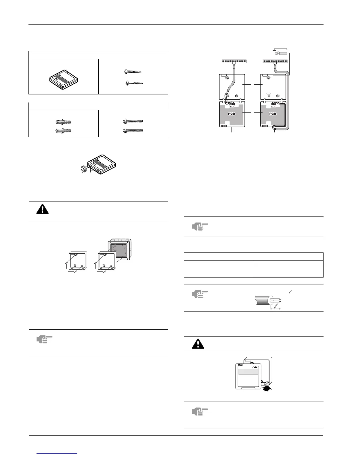
3. Wire the indoor unit
Connect the terminals on top of the upper part of the remote
controller (P1, P2), and the terminals of the indoor unit (P1,
P2). (P1 and P2 do not have polarity.)
Wiring specifications
4. Reattach the upper part of the remote
controller
First begin fitting from the clips at the bottom.
Remote controller Wood screws
Wall plugs Machine screws
The PC board is mounted in the upper part of the
remote controller. Be careful not to damage the
board with the minus screwdriver.
1
for exposed mounting, fasten with the two included wood
screws (Ø4x30) and plugs.
2
for flush-mounting, fasten with the two included machine
screws (M4x16).
NOTE
Choose the flattest place possible for the
mounting surface. Be careful not to distort the
shape of the lower part of the remote controller
by overtightening the mounting screws.
1
1 2
1 indoor unit
2 lower part of the remote controller
3 upper part of the remote controller
4 wired from the rear
5 wired from the top
6 notch the part for the wiring to pass through with nippers
NOTE
When wiring, run the wiring away from the power
supply wiring in order to avoid receiving electric
noise (external noise).
Wiring type Size
2 conductor, stranded, non-
shielded copper cable / PVC or
vinyl jacket
AWG18
NOTE Peel the shield for the part that has to pass through the
inside of the remote controller case ( ).
Be careful not to pinch the wiring when
attaching.
NOTE
1. The switch box and wiring for connection are
not included.
2. Do not directly touch the PC board with your
hand.
P2 P1 P2 P1
1 1
6
2
3
4 5
1