IM 1049-9 42 www.DaikinApplied.com
tyPiCal refrigeration CyCles
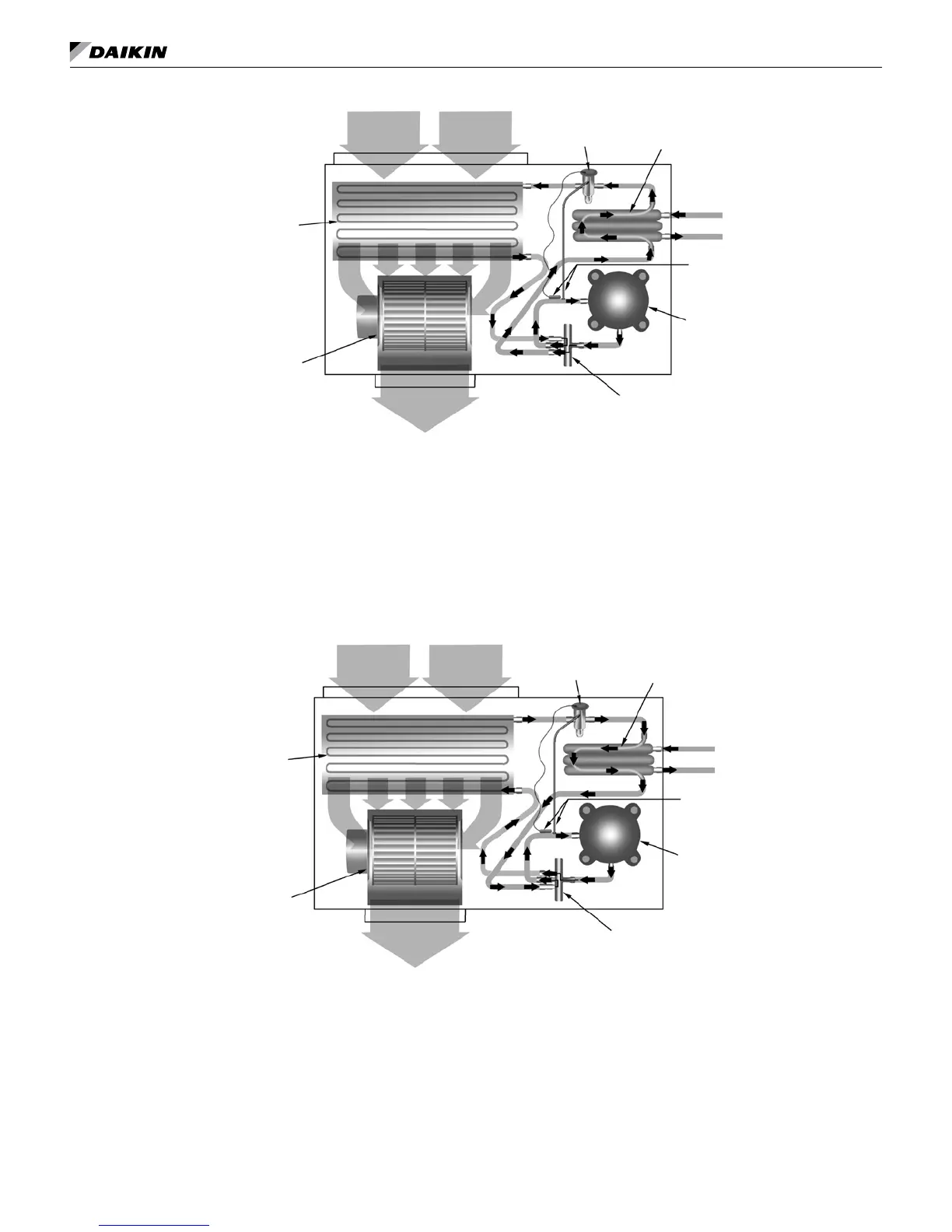
Figure 58: Cooling Mode – (Single Circuit Only Shown)
Return Air
Reversing Valve
Conditioned Air – (Cooling)
Thermal
Expansion Valve
Co-Axial Heat
Exchanger
Blower
Coil – Air to Refrigerant
Heat Exchanger
Water In
Water Out
Sensing Bulb and
Capillary Tube
Compressor
Cooling Refrigeration Cycle
WhenthewallthermostatiscallingforCOOLING,thereversingvalvedirectstheowoftherefrigerant,ahotgas,
leaving the compressor to the water-to-refrigerant heat exchanger. Here the heat is removed by the water and the
hotgascondensestobecomealiquid.Theliquidthenowsthroughathermalexpansionmeteringsystemtothe
air-to-refrigerant heat exchanger coil. The liquid then evaporates becoming a gas, at the same time absorbing heat
andcoolingtheairpassingoverthesurfacesofthecoil.Therefrigerantthenowsasalowpressuregasthroughthe
reversing valve and back to the suction side of the compressor to complete the cycle.
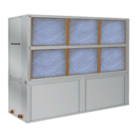
Figure 59: Heating Mode – (Single Circuit Only Shown)
Return Air
Thermal
Expansion Valve
Co-Axial Heat
Exchanger
Reversing Valve
Conditioned Air – (Heating)
Blower
Water In
Water Out
Sensing Bulb
and Capillary Tube
Compressor
Coil – Air to Refrigerant
Heat Exchanger
Heating Refrigeration Cycle
WhenthewallthermostatiscallingforHEATING,thereversingvalvedirectstheowoftherefrigerant,ahotgas,
leaving the compressor to the air-to-refrigerant heat exchanger coil. Here the heat is removed by the air passing
overthesurfacesofthecoilandthehotgascondensestobecomealiquid.Theliquidthenowsthroughacapillary
thermal expansion metering system to the water-to-refrigerant heat exchanger. The liquid then evaporates becoming a
gas,atthesametimeabsorbingheatandcoolingthewater.Therefrigerantthenowsasalowpressuregasthrough
the reversing valve and back to the suction side of the compressor to complete the cycle.