D–EIMAC00708-16EN - 38/76
Electrical components
All power and interface electrical connections are specified in the wiring diagram that is shipped with the machine.
The installer must supply the following components:
- Power supply cables (dedicated conduit)
- Interconnection and interface cables (dedicated conduit)
- Suitable line protection devices (fuses or circuit breakers, please see electrical data).
Power Circuit Wiring
A disconnect switch is factory-installed for isolating electrically the unit when switched off. Compressor overload and
short-circuit protection is accomplished by fuses installed in the electrical panel.
Proper phase sequence to the unit is required as far as the unit operation is concerned. All line-side wiring must be in
accordance with local regulation and be made with copper wire and copper lugs only. The table below is a reference only
for dimensioning protection devices and wiring.
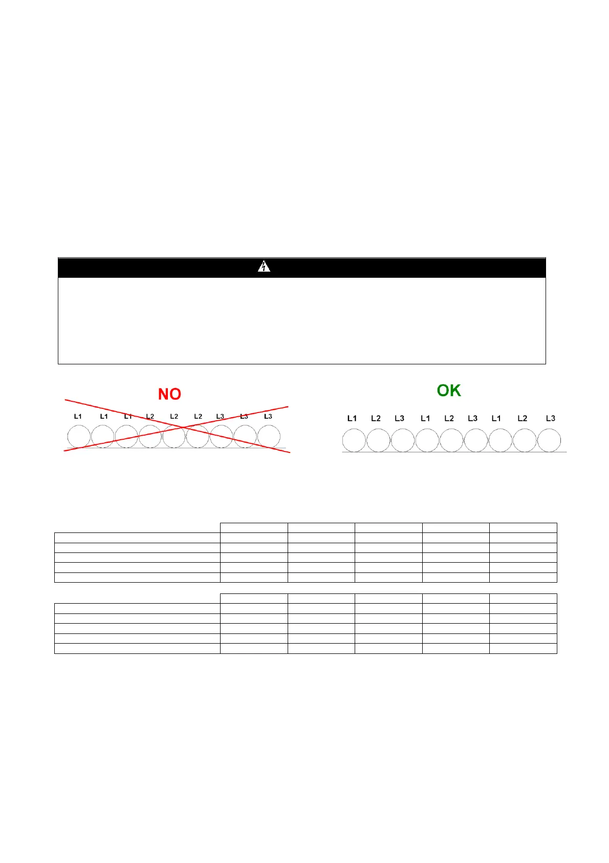
In installations with power supply lines longer than 50 metres, phase-to-phase and phase-to-earth inductive couplings
between phases generate significant phenomena, namely:
unbalancing of phase currents
excessive voltage drop
In order to limit this phenomena, it is good practice to lay out the phase wires symmetrically, as described in the
figure.
Figure 17 - Installation of long power supply wires
Table 23 - Recommended Fuses and Field Wire Sizing
EWAD 100E ÷ 410E-SS
Short circuit rating (note 1)
Minimum Recommended Wire Size (note 2)
Maximum Wire Size (note 3)
Short circuit rating (note 1)
Minimum Recommended Wire Size (note 2)
Maximum Wire Size (note 3)
Note 1:
Short-circuit current ratings are referred to a 0.25 s duration of short circuit.
Note 2:
Correct wire sizing must take into account the actual ambient temperature of the installation and the protection device installed on-site.
Recommended wire size is made according to standard EN60204-1 – Table 6.E with the following assumptions:
- Recommended protection devices (fuses)
- 70°C PVC stranded copper conductors
- 40°C ambient temperature
Wire sizing is different as installation and operation conditions are different from the above mentioned values. The voltage drop from the
point of supply to the load must not exceed 5% of the nominal voltage under normal operating conditions. In order to comply with this
requirement, it can be necessary to use conductors having a larger cross-sectional area than the minimum value reported on the above
table.
Note 3:
Maximum wire size is the maximum allowed by the disconnect switch terminals. In case a larger conductor size is needed, contact
factory for asking special incoming lugs.