6 Configuration
Installation and operation manual
13
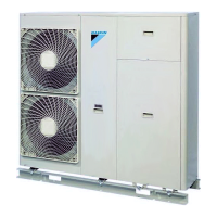
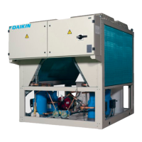
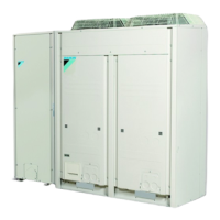
EWAQ016~064CAW + EWYQ016~064CAW
Packaged air-cooled water chiller
4P489435-1B – 2017.10
CAUTION
Do NOT pinch the wiring when attaching.
If, in addition to the standard remote controller, an optional remote
controller (EKRUAHTB) is installed as well:
5 Connect the electrical wires of both remote controllers as
described.
6 Select a master and a slave remote controller using the SS1
selector switch.
S Slave
M Master
INFORMATION
Only the remote controller set as master can be used as a
room thermostat.
INFORMATION
For multi unit control, connect the remote controller to the
unit as instructed above. For all other units to be controlled
by this controller, connect P1 of the previous unit to P1 of
the next unit, P2 of the previous unit to P2 of the next unit,
etc.
This is limited to 16 PCBs, with EWAQ+EWYQ016~032
counting as 1 PCB, and EWAQ+EWYQ040~064 as 2
PCBs.
5.4.6 To install optional equipment
For the installation of optional equipment, refer to the installation
manual which is delivered with the optional equipment or the
addenda delivered with this unit.
6 Configuration
INFORMATION
It is important that all information in this chapter is read
sequentially by the installer and that the system is
configured as applicable.
DANGER: RISK OF ELECTROCUTION
6.1 Overview: Configuration
This chapter describes what you have to do and know to configure
the system after it is installed.
It contains information about:
▪ Making field settings
▪ Switching between cooling and heating
INFORMATION
It is important that all information in this chapter is read
sequentially by the installer and that the system is
configured as applicable.
DANGER: RISK OF ELECTROCUTION
6.2 Making field settings
6.2.1 About making field settings
INFORMATION
The LEDs and buttons are located in the outdoor module
(not in the hydro module).
Making settings is done via the master unit.
Next to making field settings it is also possible to confirm the current
operation parameters of the unit.
Pushbuttons and DIP switches
Item Description
Pushbuttons By operating the pushbuttons it is possible to:
▪ Change the mode.
▪ Perform field settings (demand operation,
low noise, etc).
DIP switches ▪ DS1 (1): COOL/HEAT selector
▪ DS1 (2~4): NOT USED. DO NOT CHANGE
THE FACTORY SETTING.
▪ DS2 (1~4): NOT USED. DO NOT CHANGE
THE FACTORY SETTING.
See also:
▪ "6.2.2Field setting components"on page14
▪ "6.2.3To access the field setting components"on page14
Mode 1 and 2
Mode Description
Mode 1
(monitoring
settings)
Mode1 can be used to monitor the current
situation of the outdoor unit. Some field setting
contents can be monitored as well.
Mode 2
(field settings)
Mode2 is used to change the field settings of
the system. Consulting the current field setting
value and changing the current field setting
value is possible.
In general, normal operation can be resumed
without special intervention after changing field
settings.
Some field settings are used for special
operation (e.g., 1 time operation, recovery/
vacuuming setting, manual adding refrigerant
setting, etc.). In such a case, it is required to
abort the special operation before normal
operation can restart. It will be indicated in
below explanations.
See also:
▪ "6.2.4To access mode 1 or 2"on page14
▪ "6.2.5To use mode 1"on page14
▪ "6.2.6To use mode 2"on page15
▪ "6.2.7Mode 1: Monitoring settings"on page15
▪ "6.2.8Mode 2: Field settings"on page15
 Loading...