10 About the system
Installation and operation manual
26
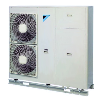
EWAQ016~064CAW + EWYQ016~064CAW
Packaged air-cooled water chiller
4P489435-1B – 2017.10
K1P Pump contactor
K1S Pump overcurrent relay
K*R (A3P) Printed circuit board relay
M1P Pump
PS (A*P) Switching power supply
Q1DI Earth leakage circuit breaker (field supply)
Q1T Thermostat for expansion vessel heater
R11T Leaving water thermistor (PHE1)
R12T Returning water thermistor (PHE1)
R13T Refrigerant liquid thermistor (PHE1)
R14T Refrigerant gas thermistor (PHE1)
R21T Leaving water thermistor (PHE2)
R22T Returning water thermistor (PHE2)
R23T Refrigerant liquid thermistor (PHE2)
R24T Refrigerant gas thermistor (PHE2)
S1F Flow switch (PHE1)
S2F Flow switch (PHE2)
S1M Main switch
S1S Thermostat ON/OFF input (field supply)
S2S Thermostat cooling/heating selection (field
supply)
S3S Operation ON input (field supply)
S4S Operation OFF input (field supply)
SS1 (A1P, A5P) Selector switch (emergency)
SS1 (A2P) Selector switch (master/slave)
SS1 (A7P) Selector switch (master/slave) (optional)
V1C, V2C Ferrite core noise filter
X1M~X4M Terminal strip
X801M (A*P) Printed circuit board terminal strip (control)
Z1F, Z2F (A*P) Noise filter
For the user
10 About the system
NOTICE
For future modifications or expansions of your system:
A full overview of allowable combinations (for future
system extensions) is available in technical engineering
data and should be consulted. Contact your installer to
receive more information and professional advice.
This small inverter chiller can be combined with fan coil units for air
conditioning purposes, or it can be used for supplying water for
process cooling applications.
10.1 System layout
Your small inverter chiller can be one of following models:
Model Description
EWAQ Air-to-water cooling only model.
EWYQ Air-to-water heat pump model.
11 User interface
CAUTION
NEVER touch the internal parts of the controller.
Do NOT remove the front panel. Some parts inside are
dangerous to touch and appliance problems may happen.
For checking and adjusting the internal parts, contact your
dealer.
a
ON/OFF button
b Quiet mode button
c Programming button
d Weather dependent setpoint button (heat pump units
only)
e Schedule timer button
f Inspection/test operation button
g
The / button is used to select the operation mode:
space heating ( ) or space cooling ( ).
h
button
i Room temperature adjust buttons
and
j Leaving water temperature adjust buttons and
k Time adjust buttons and
Icon Description
Operation LED
Lit during space heating operation. Blinks if a
malfunction occurs. When the LED is off, space
heating is inactive while the other operation modes
can still be active.
Heating mode
Cooling mode
Quiet mode
 Loading...