5 Installation
Installation and operation manual
9
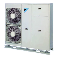
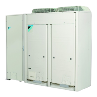
EWAQ016~064CAW + EWYQ016~064CAW
Packaged air-cooled water chiller
4P489435-1B – 2017.10
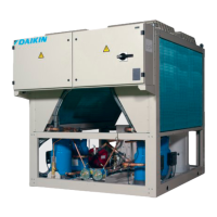
Panel
1 Electrical parts of the hydro module
2 Hydro module (side panel)
3 Hydro module (front panel)
4 Outdoor module (left panel)
5 Outdoor module (right panel)
Once the front plates open, the electrical component box can be
accessed. See "5.1.2 To open the electrical component box of the
outdoor unit"on page9.
For service purposes, the pushbuttons on the main PCB need to be
accessed. To access these pushbuttons, the electrical component
box cover does not need to be opened. See "6.2.3 To access the
field setting components"on page14.
5.1.2 To open the electrical component box of
the outdoor unit
NOTICE
Do NOT apply excessive force when opening the
electronic component box cover. Excessive force can
deform the cover, resulting in entering of water to cause
equipment failure.
5.2 Mounting the outdoor unit
5.2.1 To provide the installation structure
Make sure the unit is installed level on a sufficiently strong base to
prevent vibration and noise.
NOTICE
When the installation height of the unit needs to be
increased, do NOT use stands to only support the corners.
X Not allowed
O Allowed (* = preferred installation)
▪ The height of the foundation must at least be 150 mm from the
floor. In heavy snowfall areas, this height should be increased,
depending on the installation place and condition.
▪ The preferred installation is on a solid longitudinal foundation
(steel beam frame or concrete). The foundation must be larger
than the grey marked area.
729
765
765
631
A
B
729
765
765
631
A
B
C B
a
b
c
d
e
f
c
a
b
c
d
e
f
c
440
440
Minimum foundation
a Hole for foundation bolt
b Base inner dimension
c Distance between foundation bolt holes
d Depth of unit
e Base outer dimension
f Longitudinal foundation dimension
kW A B C
16~25 1340 792 —
32 1650 1102 —
40+50 2320 792 192
64 2940 1102 192
▪ Fasten the unit in place using four foundation bolts M12. It is best
to screw in the foundation bolts until their length remains 20mm
above the foundation surface.
 Loading...