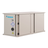
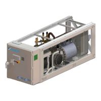
EWWQ090G ÷ EWWQ720L - R410A - Water-cooled scroll chillers
EWLQ090G ÷ EWLQ720L - R410A - Condenser less
EWHQ100G ÷ EWHQ400G - R410A - Heat pump scroll chillers
EWAQ-G 075 - R410A - Air-cooled scroll chillers
EWAQ- - R410A - Air-cooled scroll chillers
EWYQ- - R410A - Air-cooled scroll heat pumps
Air and Water cooled scroll chillers & heat pump
EWWQ - EWLQ - EWHQ
EWAQ - EWYQ
Air or Water cooled scroll chiller &
heat pump
D-EOMHW00107-15EN
Link to the compressor page
Link to the circuit condensing control page (W/C only)
Link to the circuit fan control page (A/C only)
Link to the defrost page (A/C only)
4.3.1.1 Compressors
This page resumes all the relevant information about compressors of the related circuit.
Note the following compressors enumeration:
1. Compressor 1 and compressor 3 belong to the Circuit #1
2. Compressor 2 and compressor 4 belong to the Circuit #2
Link to Compressor Enable page
Date and time of the last start
Date and time of the last stop
Running hours of compressor
Number of compressor starts
Date and time of the last start
Date and time of the last stop
Running hours of compressor
Number of compressor starts
The compressors enable page allows to enable or disable each compressor of the unit.
Enabling of the compressor
Enabling of the compressor (if available)
Enabling of the compressor
Enabling of the compressor (if available)
If a compressor is switched to off while it is in running, it does not shutdown immediately, but the
controller waits normal shutdown for thermoregulation or unit off and after the compressor disabled
will not started until it is enabled again.
4.3.1.2 Circ 1 Cond Ctrl
This page resumes all parameters for the condensing circuit control. For more details about this
parameters and the circuit condensing control logic refer to section 5.6.2.
Condensing saturated temperature setpoint
Actual condensing saturated temperature
Actual condensing control output
Maximum condensing control output
Minimum condensing control output
4.3.1.3 Fan Control (A/C only)
This page resumes all settings for the fan control. For more details about this parameters and the
fan control logic see section 5.6.3
Condensation target for fan control
Evaporation target for fan control (A/C H/P only)
 Loading...
