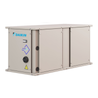
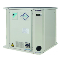
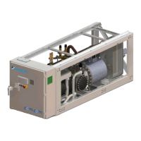
EWWQ090G ÷ EWWQ720L - R410A - Water-cooled scroll chillers
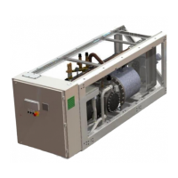
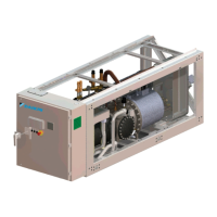
EWLQ090G ÷ EWLQ720L - R410A - Condenser less
EWHQ100G ÷ EWHQ400G - R410A - Heat pump scroll chillers
EWAQ- - R410A - Air-cooled scroll chillers
EWAQ- - R410A - Air-cooled scroll chillers
EWYQ- - R410A - Air-cooled scroll heat pumps
Air and Water cooled scroll chillers & heat pump
EWWQ - EWLQ - EWHQ
EWAQ - EWYQ
Air or Water cooled scroll chiller &
heat pump
D-EOMHW00107-15EN
4.9.5 Unit Manual Control
This page contains all the test point, status of the digital inputs, status of the digital output and raw
value of the analog inputs associated to the Unit. To activate the test point it’s required to set the
Available Modes to Test (see section 4.6).
Test of the General Alarm relay output
Test of the Evaporator Pump #1
Test of the Evaporator Pump #2
Test of the Condenser Pump #1
Test of the Condenser Pump #2
Test Valve output for condensing control
Test VFD output for condensing control
Status of the Unit Switch
Status of the Double Setpoint
Status of the Evaporator Flow switch
Status of the Condenser Flow switch
Status of the Heat Pump switch
Status of Phase Voltage monitor, Under-Over voltage protection or Ground
Fault protection (check option installed)
Status of the External Alarm
Status of the General Alarm relay
Status of the Evaporator Pump #1 relay
Status of the Evaporator Pump #2 relay
Status of the Condenser Pump #1 relay
Status of the Condenser Pump #2 relay
Resistance of the Evap EWT sensor
Resistance of the Evap LWT sensor
Resistance of the Cond LWT sensor
Resistance of the Cond LWT sensor
Current input for the Demand Limit
Current input for the Setpoint Reset
Voltage output for the valve of the condensing control
Voltage output for the VFD of the condensing control
4.9.6 Circuit 1 Manual Control
This page contains all the test point, status of the digital inputs, status of the digital output and raw
value of the analog inputs associated to the Circuit #1 (or Circuit #2 if present and depending on
the link followed). To activate the test point it’s required to set the Available Modes to Test (see
section 4.6).
Test of the compressor 1 (first compressor of the circuit number 1)
Test of the compressor 3 (second compressor of the circuit number 1)
Test of the Expansion Valve movements
Test Valve output for condensing control
Test VFD output for condensing control
Input voltage for the Evap Pressure
Input voltage for the Cond Pressure
Resistance of the Suction Temp sensor
Status of the compressor 1 (first compressor of the circuit number 1)
Status of the compressor 3 (second compressor of the circuit number 1)
Voltage output for the valve of the condensing control
 Loading...
