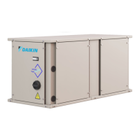
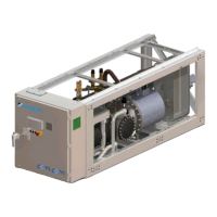
EWWQ090G ÷ EWWQ720L - R410A - Water-cooled scroll chillers
EWLQ090G ÷ EWLQ720L - R410A - Condenser less
EWHQ100G ÷ EWHQ400G - R410A - Heat pump scroll chillers
EWAQ-G 075 - R410A - Air-cooled scroll chillers
EWAQ- - R410A - Air-cooled scroll chillers
EWYQ- - R410A - Air-cooled scroll heat pumps
Air and Water cooled scroll chillers & heat pump
EWWQ - EWLQ - EWHQ
EWAQ - EWYQ
Air or Water cooled scroll chiller &
heat pump
D-EOMHW00107-15EN
each controllers, accessible on the customer terminal board. Refer to the table 1.7 for the
enumeration of the terminals.
5.10.2.2 Common leaving water temperature sensor
Common leaving water temperature sensor has to be connected to the chiller Master through the
customer terminal block (Master/Slave Temperature Sensor). Refer to the table 1.7 for the
enumeration of the terminals.
5.10.2.3 Pumps Connection
Different types of pump connections are available depending on the plant type where the Master
Slave function is used.
1. Single Common Pump
In the plant type Single Common Pump, where a unique pump provides all water flow, all enable
pump contacts of each chiller have to be connected in parallel so that it is possible to provide a
unique enabling contact for the common pump. The pump contact of each chiller is available on
the customer terminal block (Evaporator Pump #1 start). Refer to the table 1.7 for the enumeration
of the terminals.
For the water cooled unit with water inversion, remember that in heat mode the user side
pump is not the evaporator pump but the condenser pump. For this reason will be
necessary use the terminal Condenser Pump #1 start to control the common pump
2. Single Chiller Pump
In the plant type Single Chiller Pump, every pump have to be connected to the related unit. The
enabling contact is available on the customer terminal block (Evaporator Pump #1 start). Refer to
the table 1.7 for the enumeration of the terminals.
 Loading...
