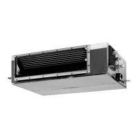
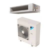
• Split Sky Air • Indoor Units
9
• Indoor Units • R-410A • FBQ-C7VEB
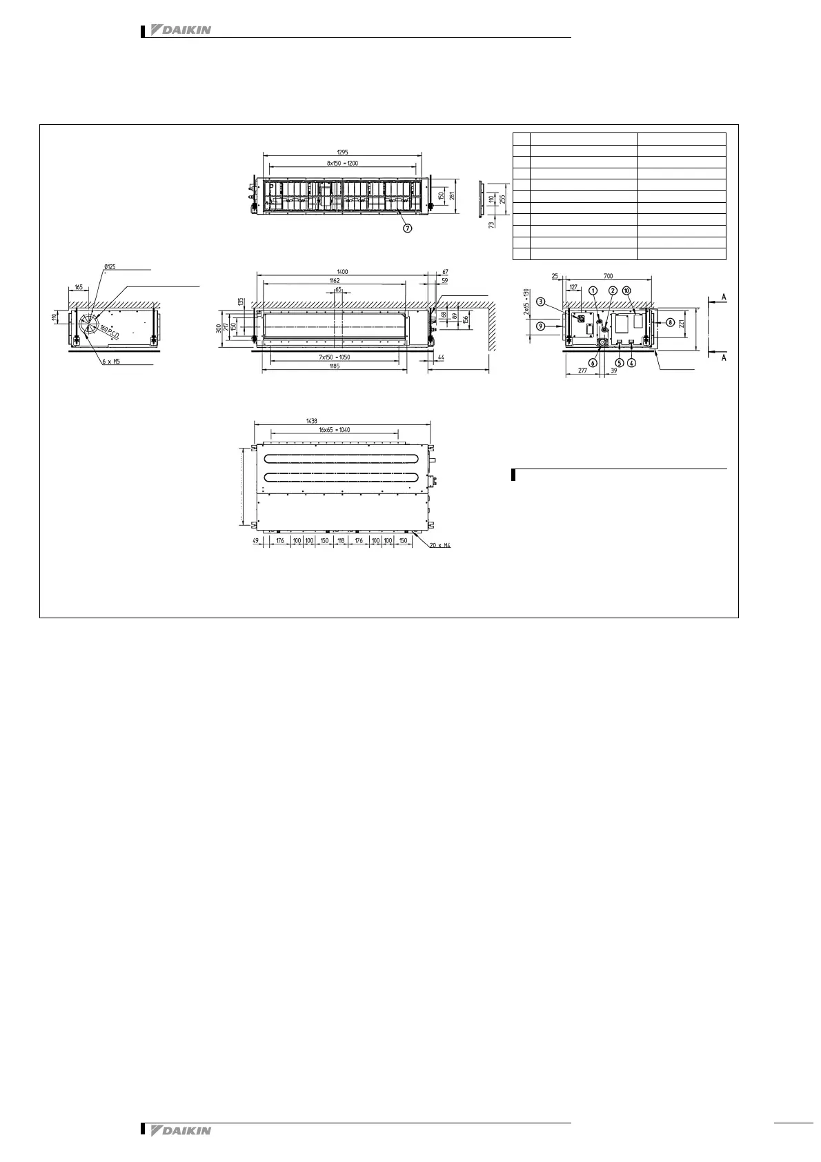
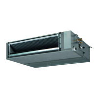
5 Dimensional drawing & centre of gravity
5 - 1 Dimensional drawing
NOTE
1 Refer to ‘outlook drawing for installing optional
accessories’ when installing optional accessories.
2 The required ceiling depth varies according to the
configuration of the specific system.
3 For maintenance of the air filter, it is necessary to
provide a service access panel.
Refer to the ‘filter installation method’ drawing.
View A-A
Detail B
Suspension bolt
(Service space)
Detail B
350 or more
(Service space)
(Suspension position)
631 (Suspension position)
500 or more
Fresh air intake position
(Knock out hole)
(On circumference)
Nr Name Description
1 Liquid pipe connection ø 9.52 flare (connection)
2 Gas pipe connection ø 15.90 (flare connection)
3 Drain pipe connection VP25 (O.D. ø 32 /I.D. ø 25)
4 Remote control wiring connection
5 Power supply connection
6 Drain hole VP25 (OD
ø 32 /I.D. ø 25
)
7 Air filter
8 Air suction side
9 Air discharge side
10 Nameplate