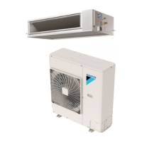
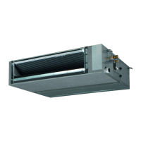
• Indoor Units • R-410A • FBQ-C7VEB
• Split Sky Air • Indoor Units
12
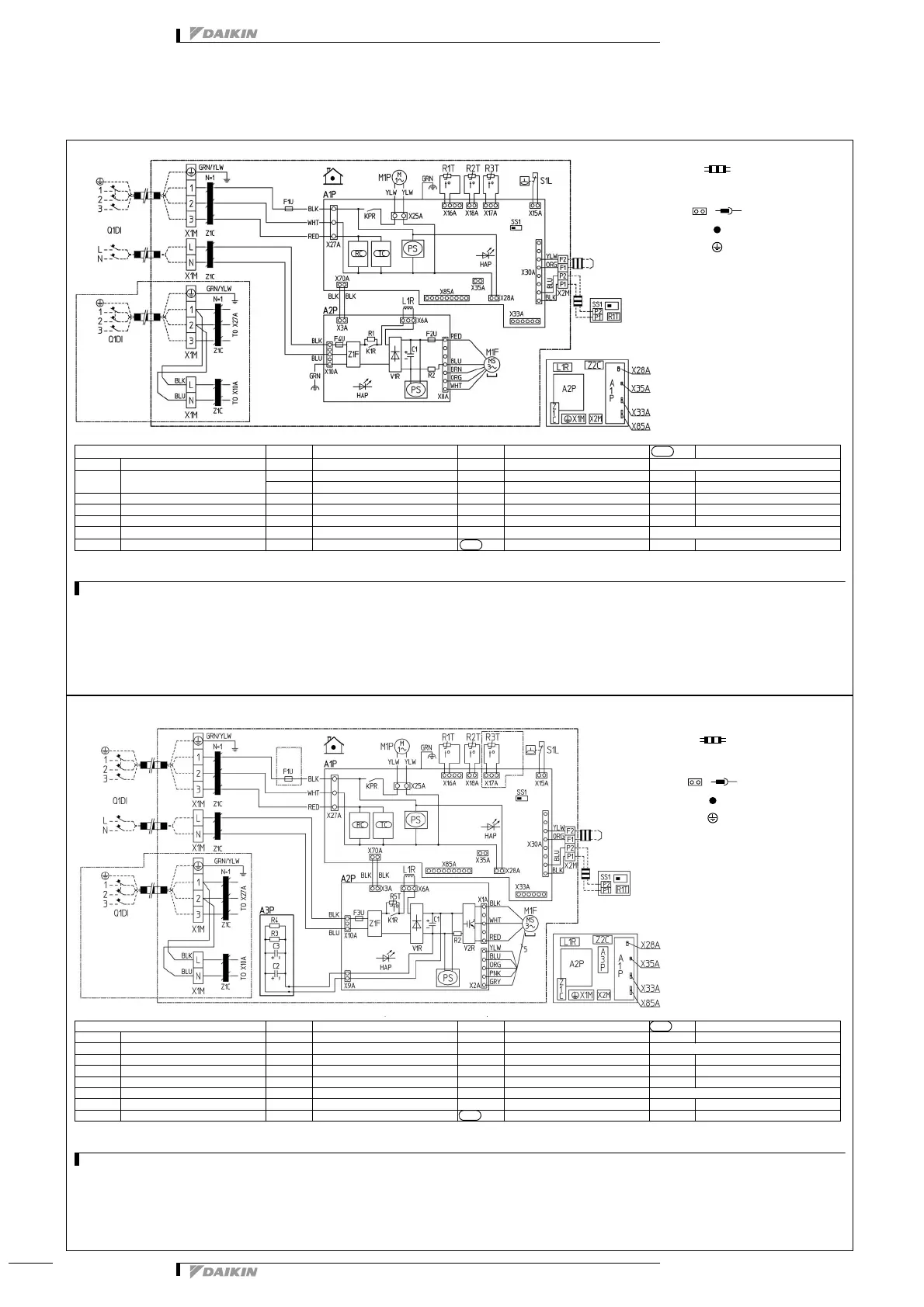
7 Wiring diagram
7 - 1 Wiring diagram
2TW31276-1A
NOTES
1 Use copper conductors only.
2 When using the central remote controller, see manual for connection to the unit.
3 The remote control model varies according to the combination system.
See technical materials and catalogues, etc. before connecting.
4 Refer to installation manual.
Indoor unit
M1F Motor (fan) SS1 Selector switch (emergency)
TC
Signal transmission circuit
A1P Printed circuit board M1P Motor (drain pump) S1L Float switch
Connector optional accessory
A2P Printed circuit board (fan) PS Switching power supply V1R Diode bridge X28A Connector (Power supply for wiring)
C1 Capacitor Q1DI Earth leak detector V2R Power module X33A Connector (for wiring)
F1U, F2U Fuse (T, 5A, 250V) R1 Resistor (current limiting) X1M Terminal strip (power supply) X35A Connector (adapter)
F4U Fuse (T, 6.3A, 250V) R2 Current sensing device X2M Terminal strip (control) X85A Connector (for multi zoning)
HAP
Light emitting diode (Service monitor green)
R1T Thermistor (suction air) Z1C Noise filter (ferrite core) X33A Connector (for wiring)
KPR, K1R Magnetic relay R2T Thermistor (liquid) Z1F Noise filter
Wired remote control
L1R Reactor R3T Thermistor (gas) RC Signal receiver circuit SS1 Selector switch (emergency)
1N~220-240V 50Hz
1N~220V 60Hz
indoor
Common
power supply
note 4
Transmission
wiring central
remote control
note 2
wired remote control
(optional accessory)
Switch box (indoor)
norm.emg
Colors
BLK : Black
BLU : Blue
BRN : Brown
GRY : Gray
ORG : Orange
PNK : Pink
RED : Red
WHT : White
YLW : Yellow
GRN : Green
: Field wiring
L
: Live
N
: Neutral
: Connector
: Wire clamp
: Protective earth
(screw)
,
FBQ35-50C7VEB
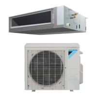
FBQ60-140C7VEB
2TW31296-1A
NOTES
1 Use copper conductors only.
2 When using the central remote controller, see manual for connection to the unit.
3 The remote control model varies according to the combination system. See technical materials and catalogues, etc. before connecting.
4 Refer to installation manual.
Indoor unit L1R Reactor R3T Thermistor (gas) TC Terminal strip (control)
A1P Printed circuit board M1F Motor (fan) R5T Thermistor NTC (Current limiting) Y1E Electronic expansion valve
A2P Printed circuit board (fan) M1P Motor (drain pump) SS1 Selector switch (emergency) Connector optional accessory
A3P Printed circuit board (capacitor) PS Switching power supply S1L Float switch X33A Connector (for wiring)
C1, C2, C3 Capacitor Q1DI Earth leak detector V1R Diode bridge X35A Connector (adapter)
F1U Fuse (T, 5A, 250V) R2 Current sensing device V2R Power module X38A Connector (for wiring)
F3U Fuse (T, 6.3A, 250V) R3, R4 Resistor (electric discharge) Z1C Noise filter (ferrite core) Wired remote control
HAP
Light emitting diode (service monitor green)
R1T Thermistor (suction air) Z1F Noise filter R1T Thermistor (air)
KPR, K1R Magnetic relay R2T Thermistor (liquid) RC Terminal strip (power supply) SS1 Selector switch (main/sub)
1N~220-240V 50Hz
1N~220V 60Hz
only for
60 class
Common
power supply
note 4
Transmission
wiring central
remote control
note 2
Wired remote control
(optional accessory)
Switch box (indoor)
NORM
.
EMG
only for
60 class
Colors
BLK : Black
BLU : Blue
BRN : Brown
GRY : Gray
ORG : Orange
PNK : Pink
RED : Red
WHT : White
YLW : Yellow
GRN : Green
: Field wiring
L
: Live
N
: Neutral
: Connector
: Wire clamp
: Protective earth
(screw)
,