428
FTX-N/U, FVXS-N, FDMQ-R Series EDUS091558E
2P126475-1
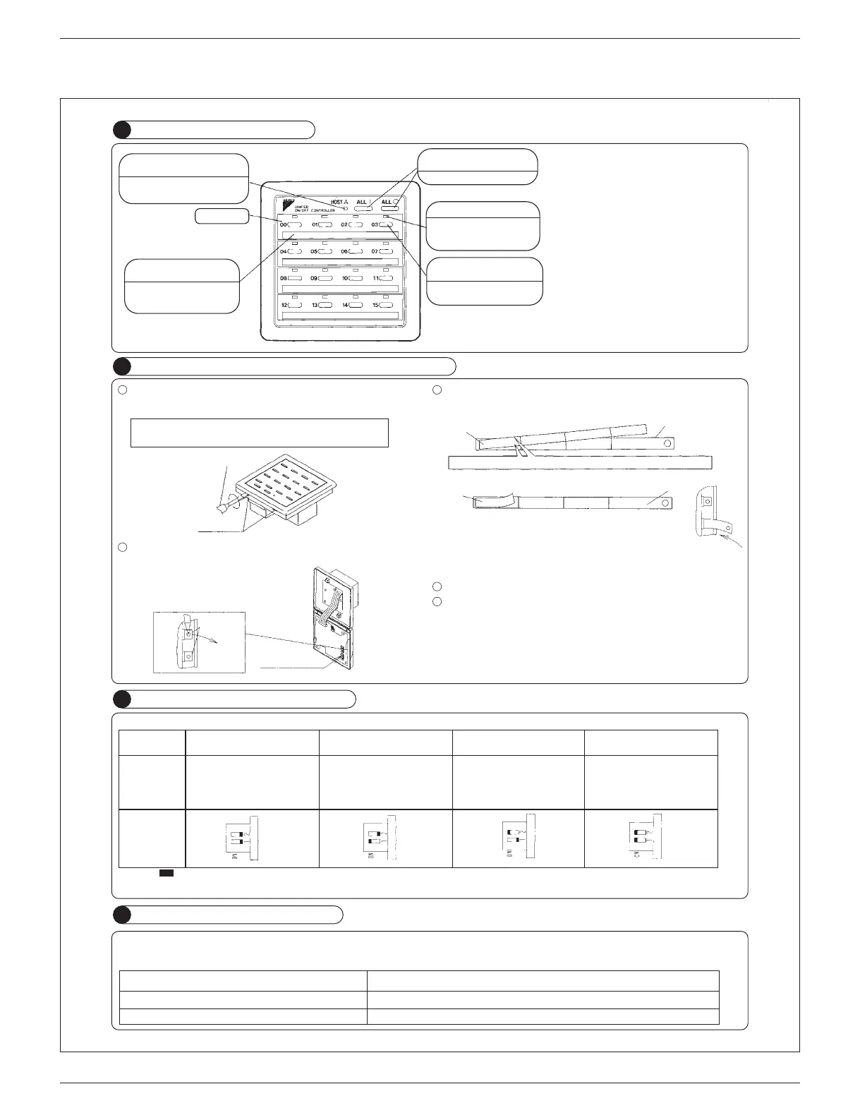
NAMES AND FUNCTIONS
1
PUTTING ROOM NAME INDICATION STICKER
DISPLAY OF MALFUNCTION
2
4
SELECTING CONTROL MODES
3
“UNDER HOST COMPUTER
INTEGRATED CONTROL” LAMP
When this lamp turns on, no
other operations are possible.
ROOM NAME INDICATION
PLATE
Refer to the “2. PUTTING
ROOM NAME INDICATION
STICKER”
GROUP NO.
UNIFIED OPERATION/STOP
BUTTON
Starts/stops all indoor units.
OPERATION LAMP
Turns on during operation of
each group and flashes
during malfunction stop.
INDIVIDUAL OPERATION/
STOP BUTTON
Starts/stops each indoor unit
group individually.
〈〈NOTE〉〉
● When using unified ON/OFF controller with other
optional controllers for centralized control,
“OPERATION LAMP” of the equipment which is
not operated may turn on or off after several
minutes.
This state occurs due to signal communications
and is not a failure.
● Do not open the upper part of remote controller
except when rewriting the indication sticker or
selecting control modes.
Open the upper part of remote controller.
Insert a (–) screwdriver into the recess between the upper and lower part of remote
controller (at 2 locations) and twist the screwdriver lightly.
Pull out the room name indication plate.
Insert the point of a mechanical pencil etc, into the hole of the indication sticker to
pull it out.
PC board is attached both the upper and lower part of remote controller.
Do not damage the board with the screwdriver.
1
Indication plate
Control mode selector
(DS2)
(–) screwdriver
(2 locations)
3
5
4
2
Flashing of lamps indicates malfunctions. Contact your Daikin dealer.
When turning power supply on, all lamps may light and UNDER HOST COMPUTER INTEGRATED CONTROL lamp may flash and not accept the operation for about on minute.
These conditions are not malfunctions.
States of lamps Contents of malfunctions
Flashing of operation lamp
Flashing of UNDER HOST COMPUTER INTEGRATED CONTROL lamp
Indicates malfunctions in the indoor unit in the group where the operation lamp is flashing.
Indicates malfunctions in optional controllers for centralized control.
The following four patterns of control mode can be set.
Control mode Individual
Centralized
Timer operation possible by
remote controller
ON/OFF control impossible by
remote controller
Content
DS2 setting
Operation/stop is controlled by both
unified ON/OFF controller and
remote controller.
After operated by unified ON/OFF
controller,operation/stop is freely
controlled by remote controller until
stopped by unified ON/OFF
controller.
When used in conjunction with schedule
timer, operation/stop is controlled freely
by remote controller during the set time
but operation is not available when
schedule timer is ON.
Operation/stop is controlled by
unified ON/OFF controller only.
Indoor units can not be operated/
stopped by remote controller.
CONTROL MODE
CONTROL MODE
CONTROL MODE
(Factory set)
NOTE:
• indicates the position of switches.
• Set control modes before turning power supply on.
• When used in conjunction with central remote controller, the control modes of the central remote controller has the priority.
CONTROL MODE
Put the attached indication sticker on the room name indication plate.
In case of serial type
Indication sticker
In case of individual type
Indication sticker
Indication plate
Indication plate
Put the sticker aligning the lines of the sticker with those of the plate.
Put the sticker on the center of the frame.
Write the room name in the frame of the sticker with a ball point pen or a felt-tip
pen (oil-base).
Reinstall the plate as it were, with checking the correct direction.
Close the upper part of remote controller.
 Loading...