FTX-N/U, FVXS-N, FDMQ-R Series EDUS091558E
449
3K019189-1D
3
42
2
2
32
5
45
2-M4
3
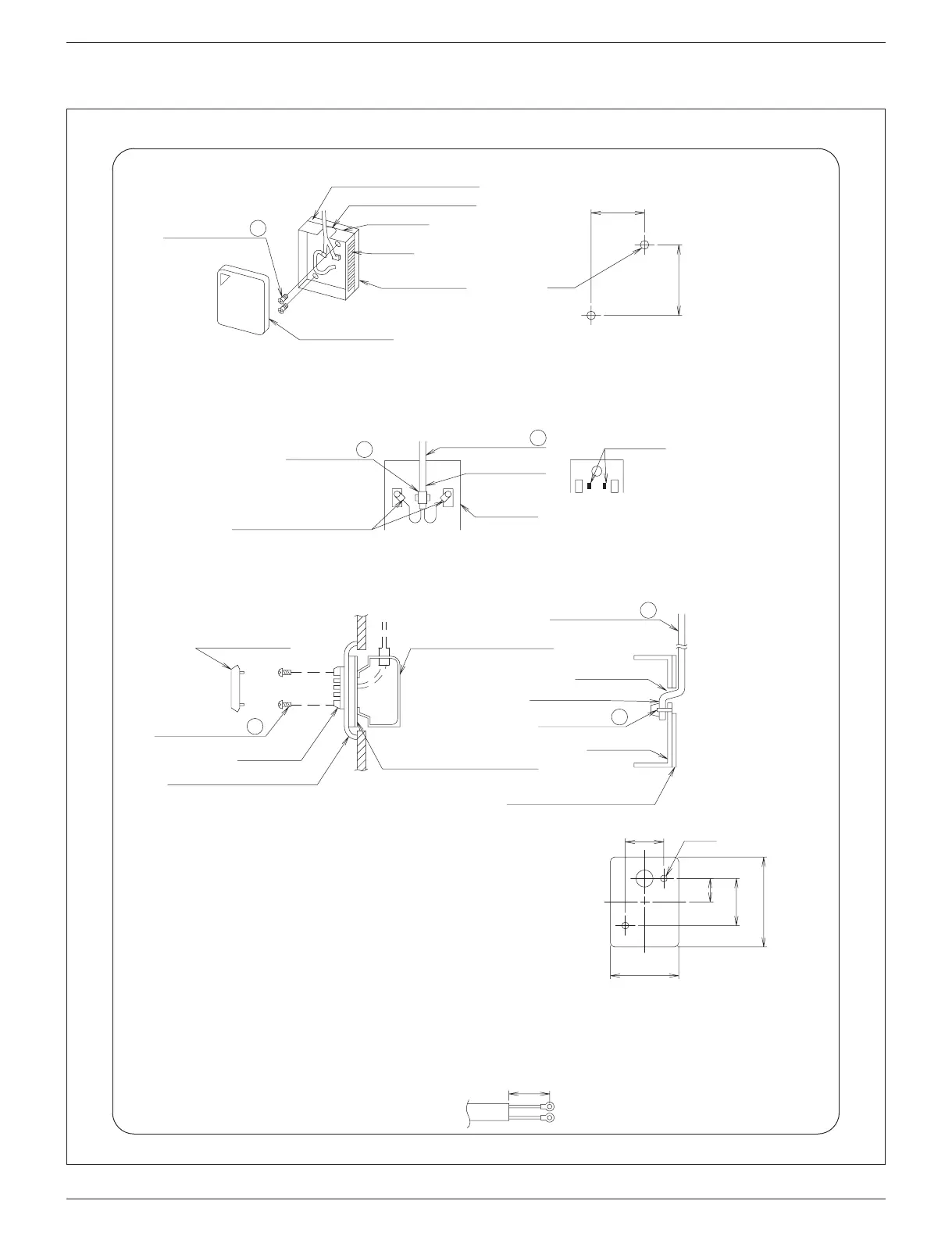
(a) When mounting on the wall
Thermal insulation material
Knockout hole for cable
Sensor box
Air hole
Released paper
Sensor box cover
Wall surface mounting holes (unit: mm)
•
Break open the knockout hole in the sensor box with a nipper or a similar tool. Pass the extension wires through the hole and
fasten the wires to the terminals with screws.
•
To avoid tensile force on the terminals, pass the attached clamp through the holes shown in the below right figure and tighten
the extension cable with the attached clamp at the sheathed part. (The knot must come to the box inside.)
•
Screw the sensor box securely to the wall surface with screws M4x16 (2 places).
If the sensor box cannot be screwed to wall surface, tear off the released paper and mount it on the wall surface.
Clamp (knot)
Extension cable
Sheathed part
Sensor box
Clamp hole
Fasten the terminals with
care to prevent the wires
from touching each other.
(b) For embedded wiring
Sensor box cover
Mounting screw
Sensor box
Metal plate
(for single unit without hole)
(field supplied)
Mounting frame which
matches with the switch box
(field supplied)
Extension cable
Through hole
Switch box (for single unit)
(field supplied)
Sheathed part
Sensor box
Clamp (knot)
Thermal insulation material
•
Pass the extension cable through the switch box cable hole and carry out the wiring.
•
Pass the attached clamp through the clamp holes and tighten the extension cable at
the sheathed part as shown in the upper right figure.
•
Tap M4 screw holes in the metal plate (field supplied) as shown in the right
drawing and mount the switch box on the metal plate.
32
2-M4
(120)
21
(70)
42
Holes to be tapped in the
metal plate on site (unit: mm)
<Cautions>
•
When wiring the extension cable, the air holes will not be blocked.
•
When the extension cable is longer than necessary, cut it to the appropriate length, peel the insulation, attach the round crimp
terminal for M3 (field supplied) and carry out the wiring. The length of insulation to be peeled off is as shown.
(Work carefully so that the connector side may not be cut.)
For M3
Round crimp terminal
5
Mounting screw
 Loading...