RXL-W Series EDUS092213A
73
3P686875-1
4
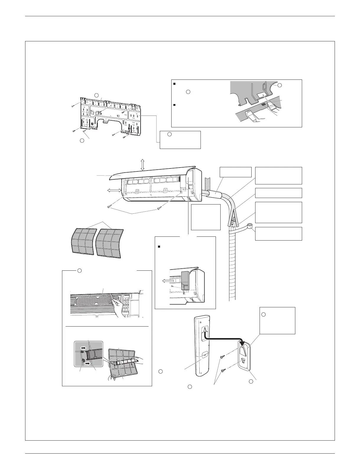
Indoor Unit Installation Diagram
09/12 class
15 class
Screws
M4 × 5/8” (M4 × 16mm)*
Service lid
Opening method
1) Remove the service lid screw.
2) Pull out the service lid horizontally in
the direction of the arrow.
3) Pull down.
Wrap the insulation pipe with
the finishing tape from bottom
to top.
Wrap with the finishing tape
so that no gap is left.
Do not connect commercially
available drain hose directly
to the indoor unit. (Water
leakage may result)
Mounting
plate
Hook
Mark (rear side)
Bottom frame
Front grille
How to attach the indoor unit
Hook the hooks of the bottom frame
to the
mounting plate.
If the hooks are difficult to hook,
remove the front grille.
How to remove the indoor unit
Push up the marked area (at the
lower part of the front grille) to
release the hooks. If it is difficult to
release, remove the front grille.
1-3/16” (30mm) or more from ceiling
Front panel
1-15/16” (50mm) or more
from walls
(on both sides)
Air filters
A
A
*The 15 class model has 3 screws.
Titanium apatite deodorizing filter (2)
C
The service lid is removable.
Filter frame
Claw
Air filter
Titanium apatite
deodorizing filter
Ta b
Mounting plate
fixing screw
M4 × 1” (M4 × 25mm)
B
Appearance of
indoor units may
differ from some
models.
(This is a 09/12
class illustration)
Caulk pipe hole gap
with putty.
Cut thermal insulation pipe to
an appropriate length and
wrap it with tape, making
sure that no gap is left in the
insulation pipe’s cut line.
A
Mounting plate
Titanium apatite deodorizing filter
Remote
controller holder
E
Remote controller
holder fixing screw
M3 × 13/16” (M3 × 20mm)
F
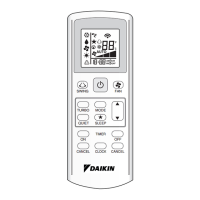
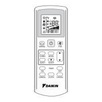
Wireless remote
controller
D
The mounting plate
should be installed on a
wall which can support the
weight of the indoor unit.
A
Before screwing the
remote controller
holder to the wall, make
sure that control signals
are properly received by
indoor unit.
E
01_EN_3P686875-1.indd 4 2022/04/28 11:02:34