SiUS041829E Indoor Unit
Part 3 Printed Circuit Board Connector Wiring Diagram 19
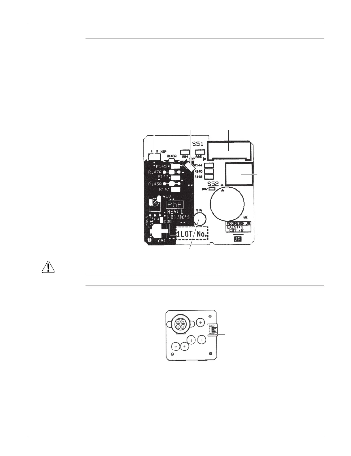
Display/Signal
Receiver PCB
(A2P)
Replace the PCB if you cut a jumper unintentionally.
Jumpers are necessary for electronic circuit. Improper operation may occur if you cut any of them.
INTELLIGENT
EYE Sensor PCB
(A3P)
1) S51 Connector for control PCB (A1P)
2) S52 Connector for room temperature thermistor
3) S1W Indoor unit ON/OFF switch
(Forced cooling operation ON/OFF switch)
Refer to page 126 for details of forced cooling operation.
4) H1P LED for operation (multi-color)
5) H2P LED for INTELLIGENT EYE (green)
6) JA Address setting jumper
Refer to page 129 for details.
S52
S51
S1W
JA
H2P
H1P
3P357402-2
1) S36 Connector for control PCB (A1P)
S36
3E860004-1
 Loading...