SiUS041829E Outdoor Unit
Part 3 Printed Circuit Board Connector Wiring Diagram 21
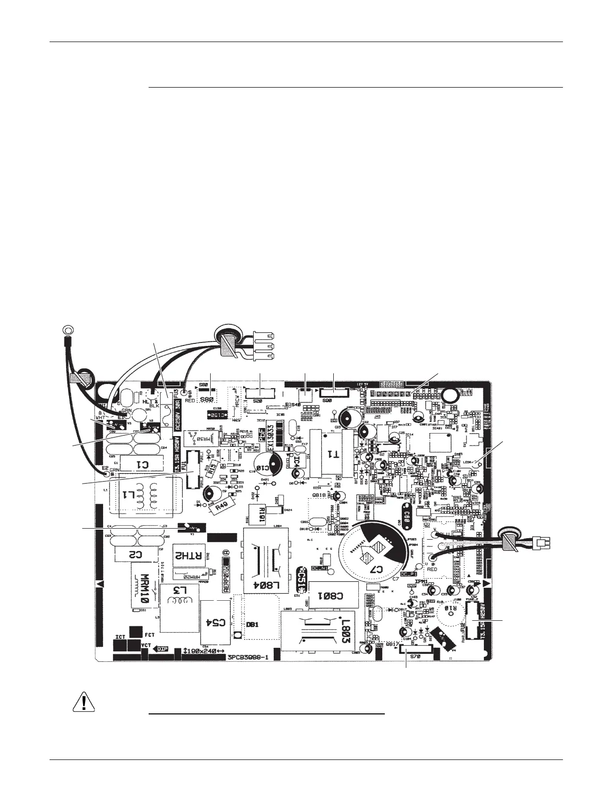
2.2 RX18RMVJU9
Main PCB
Replace the PCB if you cut a jumper unintentionally.
Jumpers are necessary for electronic circuit. Improper operation may occur if you cut any of them.
1) S20 Connector for electronic expansion valve coil
2) S40 Connector for overload protector
3) S70 Connector for DC fan motor
4) S80 Connector for four way valve coil
5) S90 Connector for thermistors
(outdoor temperature, outdoor heat exchanger, discharge pipe)
6) HL1, HN1, S Connector for terminal block
7) E1, E2 Terminal for ground
8) U, V, W Connector for compressor
9) FU1, FU2 Fuse (3.15 A, 250 V)
10) FU3 Fuse (30 A, 250 V)
11) J6 Jumper for facility setting
Refer to page 131 for details.
12) LED A LED for service monitor (green)
13) V1, V2, V3 Varistor
LED A
U, V, W
2P443814-55
FU2
V1
FU1
V3
V2
E1, E2
HL1, HN1, S
FU3
S80 S20 S40 S90 J6
S70
 Loading...