11 Disposal
Installation manual
12
CVXM-A, FVXM-A, CVXM-A9, FVXM-A9, FVXTM-A
Split system air conditioners
3P477070-2P – 2022.09
1 In cooling mode, select the lowest programmable temperature.
In heating mode, select the highest programmable temperature.
Test run can be disabled if necessary.
2 When the test run is finished, set the temperature to a normal
level. In cooling mode: 26~28°C, in heating mode: 20~24°C.
3 The system stops operating 3 minutes after the unit is turned
OFF.
10.1.1 To perform a test run using the wireless
remote control
1 Press to switch the system on.
2 Press the middle of and simultaneously.
3 Press twice to choose and confirm selection by pressing
.
Result: on the display indicates that the test run is selected. Test
run operation will stop automatically after about 30 minutes.
4 To stop operation sooner, press the ON/OFF button.
11 Disposal
NOTICE
Do NOT try to dismantle the system yourself: dismantling
of the system, treatment of the refrigerant, oil and other
parts MUST comply with applicable legislation. Units
MUST be treated at a specialised treatment facility for
reuse, recycling and recovery.
12 Technical data
▪ A subset of the latest technical data is available on the regional
Daikin website (publicly accessible).
▪ The full set of latest technical data is available on the Daikin
Business Portal (authentication required).
12.1 Wiring diagram
Translation of wiring the diagram notes
On wiring diagram Translation
Caution: When the main power is
turned OFF and then back on
again, operation will resume
automatically.
Caution: When the main power is
turned OFF and then back on
again, operation will resume
automatically.
Notice: (*) Applicable for units
with refrigerant leakage sensor
only.
Notice: (*) Applicable for units
with refrigerant leakage sensor
only.
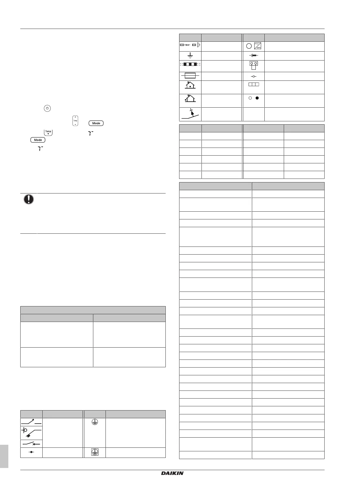
12.1.1 Unified wiring diagram legend
For applied parts and numbering, refer to the wiring diagram on the
unit. Part numbering is by Arabic numbers in ascending order for
each part and is represented in the overview below by "*" in the part
code.
Symbol Meaning Symbol Meaning
Circuit breaker Protective earth
Connection Protective earth (screw)
Symbol Meaning Symbol Meaning
Connector
,
Rectifier
Earth Relay connector
Field wiring Short-circuit connector
Fuse Terminal
Indoor unit Terminal strip
Outdoor unit Wire clamp
Residual current
device
Symbol Colour Symbol Colour
BLK Black ORG Orange
BLU Blue PNK Pink
BRN Brown PRP, PPL Purple
GRN Green RED Red
GRY Grey WHT White
SKY BLU Sky blue YLW Yellow
Symbol Meaning
A*P Printed circuit board
BS* Pushbutton ON/OFF, operation
switch
BZ, H*O Buzzer
C* Capacitor
AC*, CN*, E*, HA*, HE*, HL*,
HN*, HR*, MR*_A, MR*_B, S*, U,
V, W, X*A, K*R_*, NE
Connection, connector
D*, V*D Diode
DB* Diode bridge
DS* DIP switch
E*H Heater
FU*, F*U, (for characteristics,
refer to PCB inside your unit)
Fuse
FG* Connector (frame ground)
H* Harness
H*P, LED*, V*L Pilot lamp, light emitting diode
HAP Light emitting diode (service
monitor green)
HIGH VOLTAGE High voltage
IES Intelligent eye sensor
IPM* Intelligent power module
K*R, KCR, KFR, KHuR, K*M Magnetic relay
L Live
L* Coil
L*R Reactor
M* Stepper motor
M*C Compressor motor
M*F Fan motor
M*P Drain pump motor
M*S Swing motor
MR*, MRCW*, MRM*, MRN* Magnetic relay
N Neutral
n=*, N=* Number of passes through ferrite
core
PAM Pulse-amplitude modulation
 Loading...