5 Unit installation
Installation manual
6
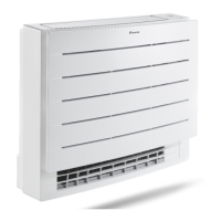
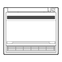
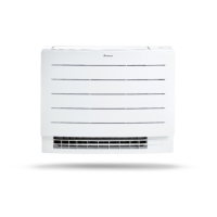
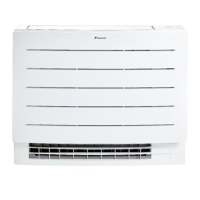
CVXM-A, FVXM-A, CVXM-A9, FVXM-A9, FVXTM-A
Split system air conditioners
3P477070-2P – 2022.09
Example: If the indoor unit is installed in room with floor area
4.99 m
2
, ceiling height 2 m, located above ground level, than the
total refrigerant change is ≤2.3kg.
5.2 Mounting the indoor unit
5.2.1 To install the indoor unit
Installation options
There are 3 possible type of installation for the indoor unit.
A Floor (exposed) installation
B Wall (exposed) installation
C Half concealed installation
a Mounting plate
b Skirting board
Floor-standing installation
(mm)
627.5
750
006
300
200
285
115
159
238
689
a
a
a
a
159
a
a
75
06
75
45
Ø65
Ø65
45
b
c
75
75
54
f
e
A B
C
54
45
d
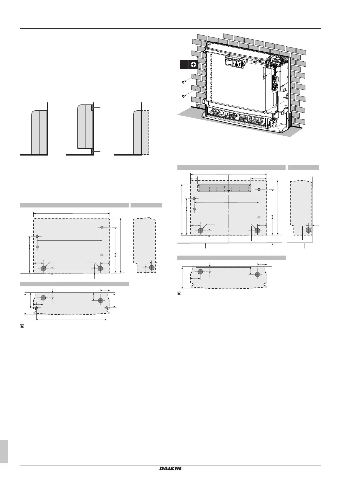
5‒1 Indoor unit installation drawing: Floor-standing installation
A Front view
B Side view
C Top view
a Screw hole 6×
b Left-back piping hole location
c Right-back piping hole location
d Left/right piping hole location
e Left-bottom piping hole location
f Right-bottom piping hole location
1 Drill a wall hole, depending on which side piping is taken out.
See "5.2.2To drill a wall hole"[48].
2 Open the front panel and remove the front grille.
3 Remove the slit portions using nippers. See "5.2.3 To remove
the slit portions"[48].
4 Secure the unit to the wall and floor using 6 screws M4×25L
(field supply).
5 When the complete installation is finished, attach the front panel
and the front grille in their original position.
Wall-mounted installation
82
166
06≤
(mm)
627.5
750
006
553
300
200
285
115
238
b
b
b
b
75
06
75
45
Ø65
Ø65
45
d
e
75
75
54
h
g
54
45
f
A B
C
c c
a
5‒2 Indoor unit installation drawing: Wall-mounted installation
A Front view
B Side view
C Top view
a Mounting plate
b Screw hole 4×
c Floor
d Left-back piping hole location
e Right-back piping hole location
f Left/right piping hole location
g Left-bottom piping hole location
h Right-bottom piping hole location
6 Temporarily secure the mounting plate on the wall.
7 Make sure the mounting plate is level.
8 Mark the centres of the drilling points on the wall.
9 Secure the mounting plate on the wall using 5 screws M4×25L
(field supply).
 Loading...