2-34
020 E417
Alarm
Logic
Power voltage sensor PT failure
Possible
Causes
1. Open circuit between connector X61A (PT/CT board)〜 X4A (CPU board)
2. Fuse F11U is open (on PT/CT board)
3. Voltage sensor PT failure (on PT/CT board)
Trouble
Shooting
Step 1. Check connector X61A (PT/CT board) and X4A (CPU board).
Make sure it is properly connected.
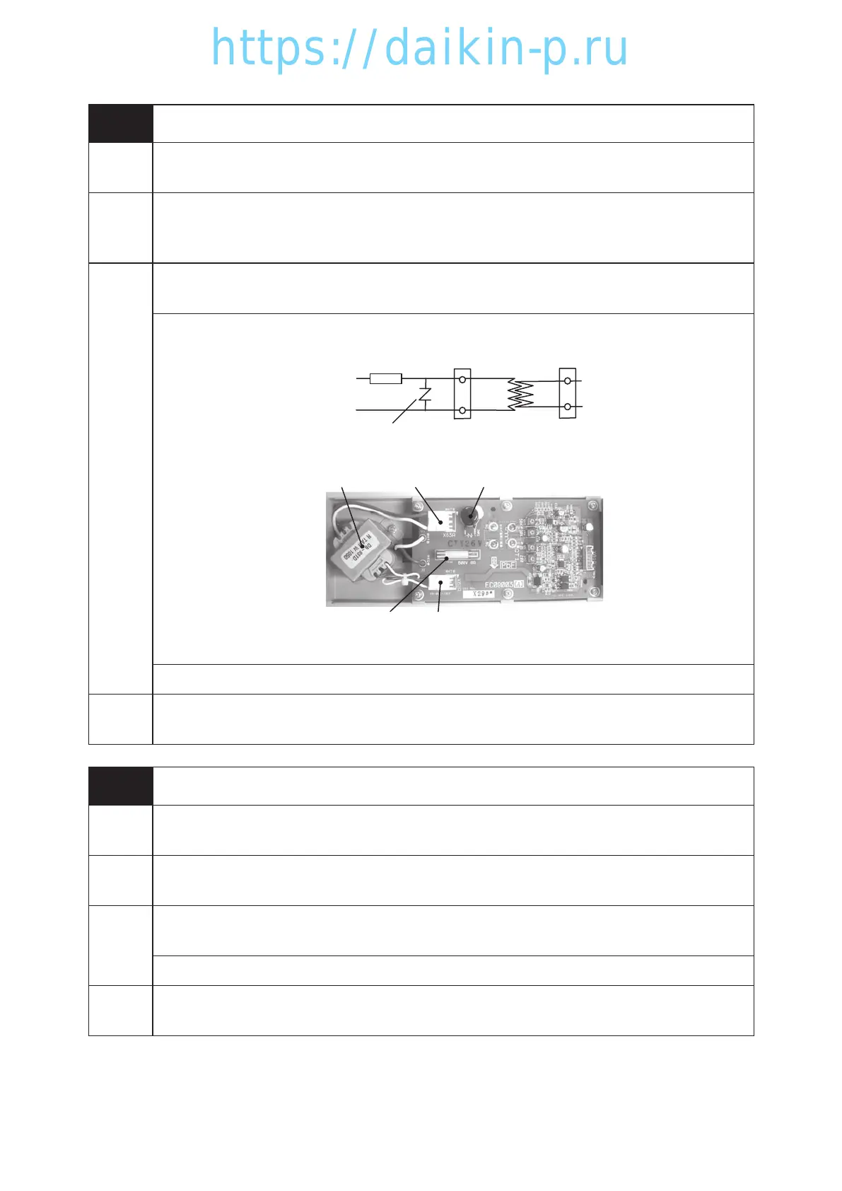
Step 2. Check if there is short circuit in secondary side of fuse F11U (ZNR, primary side of Tr).
F11U
ZN
Surge absorber
R
X62A X63A
Tr
PT/CT board
ZNRX63ATr
F11U X62A
If shorted, replace the PT/CT board.
Step 3. If repeat the alarm with no short circuit, replace the PT/CT board.
Controller
Action
E417 Alarm display only
021 E419
Alarm
Logic
Current sensor CT failure
Possible
Causes
*Open circuit between connector X61A (PT/CT board)〜 X4A (CPU board)
*Current sensor CT failure(in PT/CT board)
Trouble
Shooting
Step 1. Check connector X61A(PT/CT board) / X4A(CPU board) and make sure it is properly
installed.
Step 2. Replace PT/CT board.
Controller
Action
E419 Alarm display only
02章19-44LX10F11B3TR16-02En.indd2-3402章19-44LX10F11B3TR16-02En.indd2-34 2016/02/0217:17:392016/02/0217:17:39
 Loading...