2-36
023 E431
Alarm
Logic
Humidity sensor (HuS) failure (Detect RH>120% or RH<20%)
Possible
Causes
*Humidity sensor (HuS) deteriorated
*Contact failure of connector X20A (CPU board)
*Controller failure
Trouble
Shooting
Step 1. Replace the humidity sensor.
Step 2. Check connector X20A (CPU board) and connector on the Humidity sensor cable
located below fan deck.
Make sure it is properly connected.
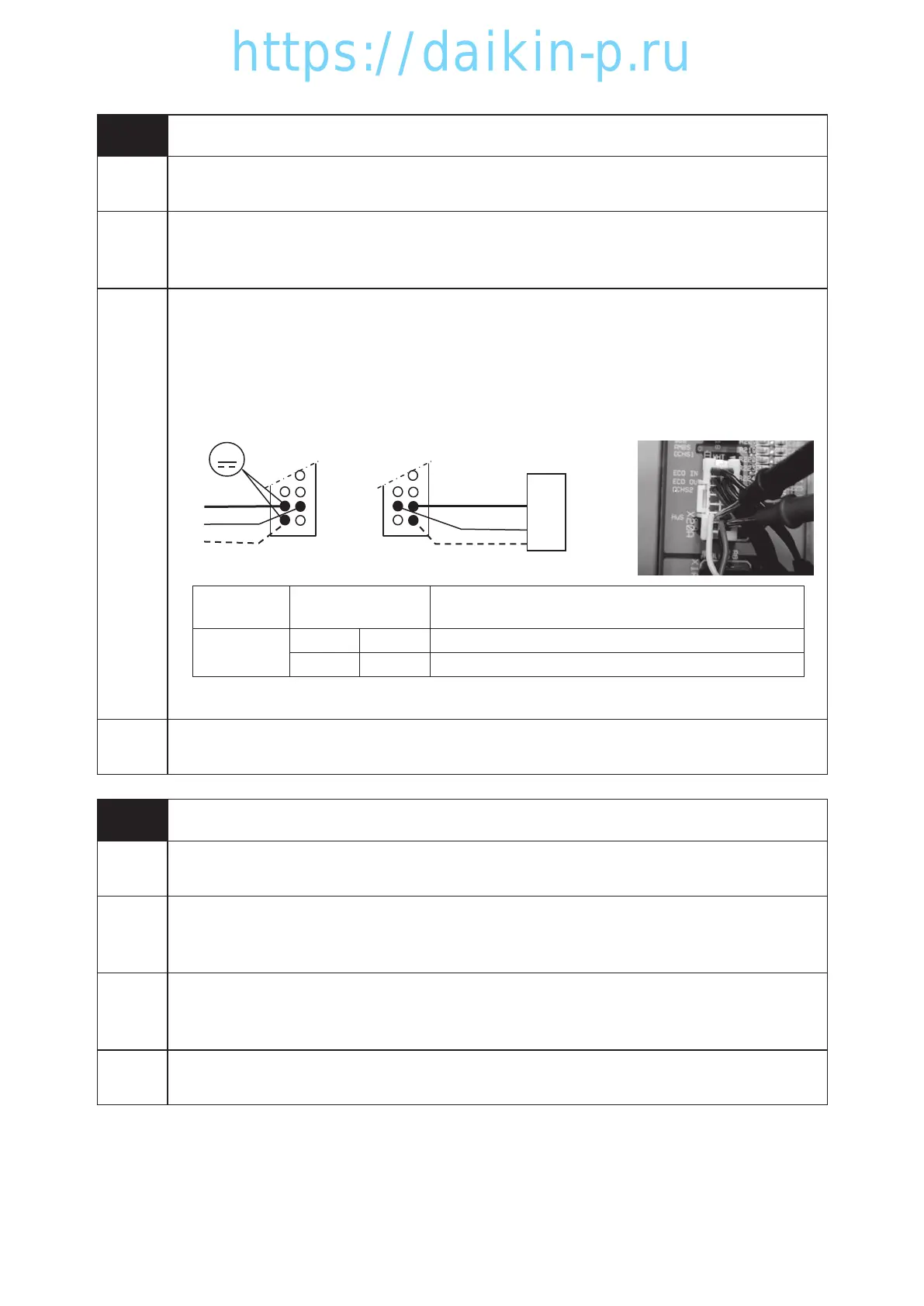
Step 3. Turn on the circuit breaker and check if there is DC5V input from the controller.
X20A
V
CPU board
DC 5V
HuS
Black
Red
Yellow
10
14
12
9
13
11
Black
Red
Yellow
Black – Red
Black – Yellow
: Input Voltage DC5V
: Output Voltage
Example of voltage check
(Connector X20A)
Sensor
name
Pin No.
(Connector X20A)
Voltage value
Humidity
sensor
11 13 DC 5V
12 13 refer to 5.4 Humidity Sensor Characteristics
Step 4. Replace the CPU board.
Controller
Action
E431 Alarm display only
024 E607
Alarm
Logic
*Sheet key failure
Possible
Causes
*Sheet key (EC6) failure
* Faulty cable or connection between Sheet key (EC6) 〜Relay board (EC5) 〜Operation
board (EC3)
Trouble
Shooting
1. Disconnect cable connectors of sheet key, relay board, and operation board, and check
connector pins visually, and secure insert correctly.
2. Replace the sheet key if the alarm is repeated.
Controller
Action
E607 Alarm display only
02章19-44LX10F11B3TR16-02En.indd2-3602章19-44LX10F11B3TR16-02En.indd2-36 2016/02/0217:17:402016/02/0217:17:40
 Loading...