www.DaikinApplied.com 11 OM 752-4
GettInG started
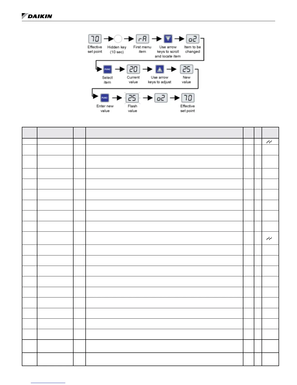
Figure 5: Changing a keypad/display menu item
Table 7: Keypad/display menu item list
Display
Keypad menu
item list
Abr. Description
RO
RW
1
06 Default
ra
Reset Alarm Input Enter 1 to clear alarms (clears all inactive alarms, except lter alarm). To enable the alarm again, enter 0. RW x
2
hc
UVC (Heat/Cool)
Mode Output
UVCM Display current UVC mode. 1 = Heat, 3 = Cool, 4 = Night Purge, 6 = Off, 8 = Emerg. Heat, 9 = Fan Only RO x
st
UVC State Output UVCS
Display current UVC state. 1 = EconMech, 2 = Mech, 3 = Econ, 4 = DA Heat, 5 = Heat, 6 = ActiveDe-
hum, 7 = Full Heat, 8 = Night Purge, 9 = Off, 10 = Fan Only, 11 = Heat Mode Cant Heat, 12 = CantCool,
13 = Emerg Heat Mode Cant Heat, 14 = Heat Mode Low Limit, 15 = Cool Mode Low Limit
RO x
d0
Discharge Air Temp
Set point Output
DATS Display current DA temperature set point. RO x
d1
Discharge Air Temp
Output
DAT Display current DA temperature. RO x
d2
Ventilation Cooling
Low Limit set point
VCLL Adjust economizer cooling DA temperature low limit. RW x
54°F
(12°C)
d3
Mechanical Cooling
Low Limit set point
MCLL Adjust mechanical cooling DA temperature low limit. RW x
45°F
(7°C)
sl
Slave Type
Conguration
Set slave type: 0 = Independent (slave uses own sensors), 1 = Dependent (slave follows master). This
feature requires a network over which the master and slave UVCs can communicate.
RW x 0
e0
Effective Occupancy
Output
Display current occupancy. RO x
xc
Occupancy Override
Input
Set occupancy: 0 = occupied, 1 = unoccupied, 2 = bypass, 3 = standby. Adjusting this variable is
intended only for troubleshooting. Once you are done, cycle unit power to clear this variable and return
the UVC to normal operation.
RW x
2
cx
Occupied Cooling set
point
OCS Adjust occupied cooling set point. RW x
73.4°F
(23°C)
cs
Standby Cooling Set
point
SCS Adjust standby cooling set point. RW x
77°F
(25°C)
cu
Unoccupied Cooling
Set point
UCS Adjust unoccupied cooling set point. RW x
82.4°F
(28°C)
hx
Occupied Heating Set
point
OHS Adjust occupied heating set point. RW x
69.8°F
(21°C)
hs
Standby Heating Set
point
SHS Adjust standby heating set point. RW x
66.2°F
(19°C)
hu
Unoccupied Heating
Set point
UHS Adjust unoccupied heating set point. RW x
60.8°F
(16°C)
rs
Wall Sensor Type Set wall sensor type: 0 = +/–3F, 1 = 55°F to 85°F. RW x 0
x1
Outside Air Damper
Position Output
OADP Display OA damper position. RO x
x2
OAD Min Position
High-Speed Set point
OADH
Adjust OA damper minimum position with IAF at high speed. (This variable is factory set to 5% open
when the unit is ordered with optional CO
2
DCV.)
RW x 20%
x3
OAD Min Position
Med-Speed Set point
OADM
Adjust OA damper minimum position with IAF at medium speed. (This variable is not used when the op-
tional CO
2
DCV is enabled. Only OADH is active as the OA damper minimum regardless of fan speed.)
RW x 25%
x4
OAD Min Position
Low-Speed Set point
OADL
Adjust OA damper minimum position with IAF at low speed. (This variable is not used when the optional
CO
2
DCV is enabled. Only OADH is active as the OA damper minimum regardless of fan speed.)
RW x 30%