4 IM 962-2
Introduction
Introduction
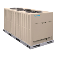
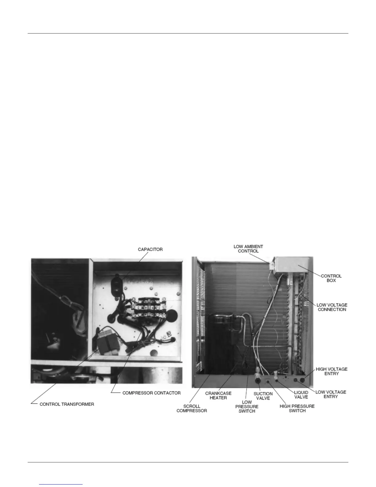
Standard Unit Features
Cabinet — Galvanized steel with a durable powder paint
nish. Stamped louvered panels offer 100% protection for the
condenser coil.
Compressor — Hermetically sealed scroll compressors.
Compressors are mounted on rubber-in-shear pads to reduce
vibration and noise.
Condenser Coil — Constructed with copper tubes and
aluminum ns mechanically bonded to the tubes for
maximum heat transfer capabilities. All coil assemblies are
leak tested at 450 psig internal pressure.
Refrigerant Connections — Field piping connections are made
through a xed panel. This allows complete access or removal of
access panels after piping connections have been made.
Crankcase Heater — Standard, all models.
Low Ambient Control — A pressure sensitive fan cycling
control to allow unit operation to 0°F is standard.
Service Valves — Standard on liquid lines and vapor lines.
Service Access — The control box, as well as the
compressor and other refrigerant controls, is accessible
through access panels. It may be opened without affecting
the normal operation of the unit. Condenser fan motors are
accessible by removing wire grilles.
Filter Drier — Field supplied.
Sight Glass — Optional, eld supplied.
Transformer — Step down type, line to 24 volts.
Contactor — The contactor is an electrical switch which
operates the compressor and condenser fans.
High Pressure Control — Opens the contactor circuit on
high refrigerant pressure; manual reset.
Low Pressure Control — Stops compressor operation in the
event of loss of refrigerant.
Condenser Fan Motor (Direct Drive) — Ball bearing 1075
RPM motors are mounted to minimize vibration and noise
problems.These are permanent split capacitor types and
require the same capacitance for both run and start.
Testing — All units are run tested at the factory prior to
shipment. Units are shipped with a holding pressure of nitrogen.
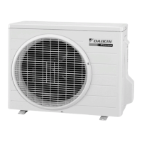
Figure 1: RCS 06F & 07F Ton Features
 Loading...