Do you have a question about the Daikin RCS Series and is the answer not in the manual?
Provides warnings and cautions for hazardous situations.
Instructions for inspecting the unit upon delivery.
Explains the model naming convention and component codes.
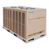
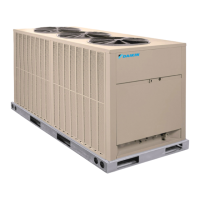
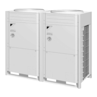
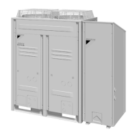
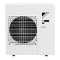
Details cabinet, compressor, coil, connections, and fan motor features.
Explains low ambient control, service valves, contactor, and pressure controls.
Details dimensions and weights for 6.5 and 7.5 ton units.
Details dimensions and weights for 10 and 12.5 ton units.
Details dimensions and weights for 15 and 20 ton units.
Table detailing capacity, weight, compressor, fan, coil, and cabinet specs.
Information on power wiring, control box, and field connections.
Advises on location, clearances, corrosive environments, and general practices.
Covers rooftop, slab installation, and rigging procedures.
Specific considerations for rooftop and slab installations.
Illustrates proper rigging procedures for lifting units.
Instructions and recommendations for refrigerant piping.
Provides piping data, recommendations, and clamp installation.
Charts for liquid/vapor line sizing and pressure drop.
Illustrates typical drain piping configurations.
Discusses electrical power, wiring, routing, and field connections.
Diagrams showing coil placement relative to the condensing unit.
Details thermostat wiring, wire sizing, and grounding procedures.
Procedure for leak testing and basic system charge.
Details R410A properties, tools, and safety precautions.
Quick reference for R410A refrigerant servicing.
Step-by-step guide for system evacuation and charging.
Troubleshooting tips for charging and a pre-start checklist.
Procedure for performing final leak testing after charging.
Instructions for installing louvered panels and optional service valves.
Explains the function of key components like contactors and safety switches.
Covers refrigerant and water piping maintenance, and crankcase heaters.
Guides to replacement parts, charging, wiring, and troubleshooting.
Chart for charging a 6.5 ton unit based on pressures.
Chart for charging a 7.5 ton unit based on pressures.
Chart for charging a 10 ton unit based on pressures.
Chart for charging a 12 ton unit based on pressures.
Chart for charging a 15 ton unit based on pressures.
Chart for charging a 20 ton unit based on pressures.
Wiring schematic for 6.5 and 7.5 ton models.
Wiring schematic for the 10 ton model.
Wiring schematic for 12.5, 15, and 20 ton models.
Details on replacement parts, compressor warranty, and return procedures.
Fields for unit details, installation, and initial checks.
Sections for recording unit performance data like voltage and amperage.
Recording operational pressures/temps and completing the registration form.
Questionnaire for rating product appearance, fit, function, and overall quality.
Details on training, warranty, and aftermarket services.