IM 738-2 43
Mechanical Installation: RFS/RCS Permanent Split Systems
such that only liquid leaves the tank but vapor enters the
compressor.
This is especially true with R-407C because the char
ge must
be drawn from the liquid portion of the tank.
Refrigerant Charge
Each unit is designed for use with R-22 or R-407C.The total
charge per circuit is the sum of the following four values:
• Condens
er section charge, see Table 13 on page 40.
• Evaporator coil char
ge, see Table 13 on page 40.
• Char
ge for length of unit piping to the evaporator coil, see
Table 13 on page 40.
• Ch
arge for length of interconnecting piping between the
RCS and RFS uni
ts, installed by field, see Table 17 on
page 41.
The exact charge for a one piece RPS/RDT is on the unit
nam
eplate.
Note: The total operating charge per circuit should not exceed
the pumpdown capacity per circuit, shown in Tables 13
to 17 on pages 40 to 41.
Subcooling
When field charging the unit, use the following to properly
charge the unit:
• All compres
sors on each circuit operating at full capacity.
• Allo
wable subcooling ranges are between 13°F to 20°F.
• Be sure to
measure pressure and temperature at the same
location when
finding/calculating subcooling. Compare th
e
actual temperature and
pressures to the saturated liqui
d
temperature. R-407C example: A
pressure of 250 psi is
measured at the condenser outlet. From the R-407C char
t,
2
50 psig is approximately 108°F saturated liquid
temperature. If the actual refrigerant temperature is 98°F,
the
l
iquid is subcooled 10°F.
• Ambient temperature must be bet
ween 60°F and 105°F.
• H
ot Gas Bypass NOT operating (only if unit is supplied with
option)
• Speed
Trol motors operating at 100% (only if unit is supplied
w
ith option)
If any one of the above items is not followed, subcooling
readings
will not be accurate and the potential exists for over or
undercharging of the refrigerant circuit.
Refrigeration Service Valves
The unit is shipped with all refrigeration service valves closed.
RDT, RPS and RCS units have the following:
Sizes 15 to 105—O
ne discharge valve is provided per
refrigerant circuit, located between the compressors and
condenser.
Sizes 115 to 135—O
ne service valve is provided on the
discharge and suction of each compressor.
All Units—One liq
uid valve is provided per refrigeration
circuit, located at end of condensing section opposite
condenser control box.
RFS units do not ship with service valves installed. Before
attempting to start the compressors, all refrigeration service
valves should be fully opened and backseated.
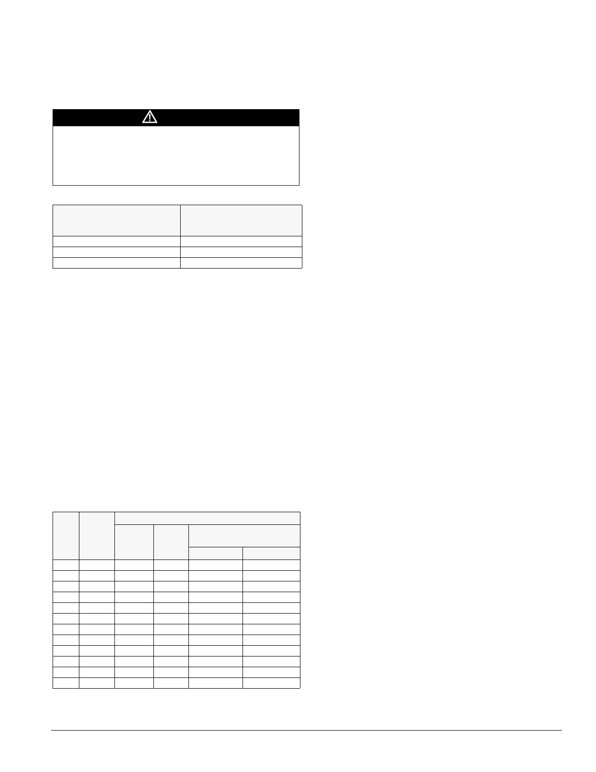
CAUTION
Units purchased for R-22 operation must be charged only
with R-22. Units purchased for R-407C operation must be
charged only with R-407C.
Field mixing or changing of refrigerants can compromise
performance
and damage equipment.
Table 19: Acceptable refrigerant oils
R-22 (mineral oils)
Note: Do not use mixtures of
mineral oils and POE oils with R-22.
R-407C (polyolester [POE] oils)
Note: Do not use mineral oils with
R-407C.
Sunisco 3GS Copeland ULtra 22 CC
Texaco WF32 Mobil EAL™ Arctic 22 CC
Calumet R015 ICI EMKARATE RL™ 32CL
Table 20: Weight of refrigerant R-22 in copper lines
(pounds per 100 feet of Type L tubing)
O.D.
line
size
Vol. per
100 ft.
in cubic
feet
Weight of refrigerant, lbs./100 feet
Liquid @
100°F
Hot gas
@ 120°F
cond.
Suction gas (superheat to
85°F)
30°F 40°F
3/8" 0.054 3.84 0.202 0.052 0.077
1/2" 0.100 7.12 0.374 0.098 0.143
5/8" 0.162 7.12 0.605 0.158 0.232
7/8" 0.336 24.00 1.260 0.323 0.480
1 1/8" 0.573 40.80 2.140 0.550 0.820
1 3/8" 0.872 62.10 3.260 0.839 1.250
1 5/8" 1.237 88.00 4.620 1.190 1.770
2 1/8" 2.147 153.00 8.040 2.060 3.060
2 5/8" 3.312 236.00 12,400 3.180 4.720
3 1/8" 4.728 336.00 17.700 4.550 6.750
3 5/8" 6.398 456.00 24.000 6.150 9.140
4 1/8" 8.313 592.00 31.100 8.000 11.190