IM 738-2 5
Introduction: Refrigeration Piping
Refrigeration Piping
This section presents the unit refrigeration piping diagrams for
the various available configurations.
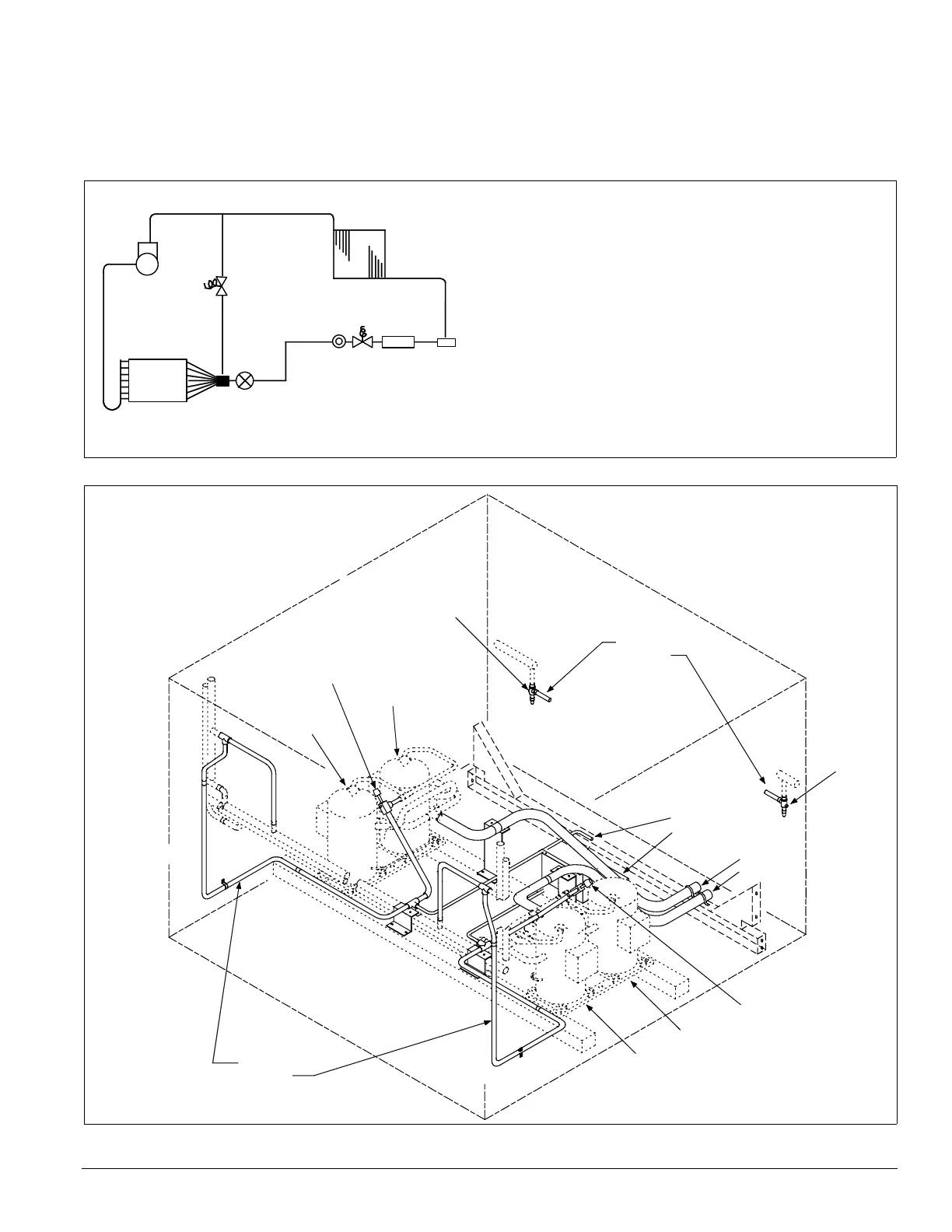
Figure 5. Circuit schematic
Figure 6. Condenser piping, scroll compressors, one to three compressors per circuit are provided (015 to 105C)
B
A
J
D
L
K
N
M
C
H
G
F
I
E
A Compressor (1, 2, or 3 per circuit)†
B Discharge line †
C Condenser coil †
D Evaporator coil*
E Manual shutoff valve†
F Filter-drier*
G Liquid line solenoid valve*
H Sightglass*
I Liquid line*†
J Suction line
K Thermal expansion valve*
L Distributor*
M Hot gas bypass and solenoid valve (optional)*†
N Hot gas bypass lines (optional)* †
*Supplied on RFS unit
s
†Su
pplied on RCS units
Compressor #1
Compressor #3
Compressor #2
Compressor #4
1
2
3
4
Discharge lines
Circuit #1
Circuit #2
Liquid lines
Circuit #1
Circuit #2
Optional
hot gas
bypass
lines
Circuit #1
Circuit #2
Suction
lines
Circuit #1
Circuit #2
Legend
1 - Discharge shut-off valve—Circuit #1
2 - Liquid shut-off valve—Circuit #1
3 - Liquid shut-off valve—Circuit #2
4 - Discharge shut-off valve—Circuit #2
 Loading...


