62 IM 738-2
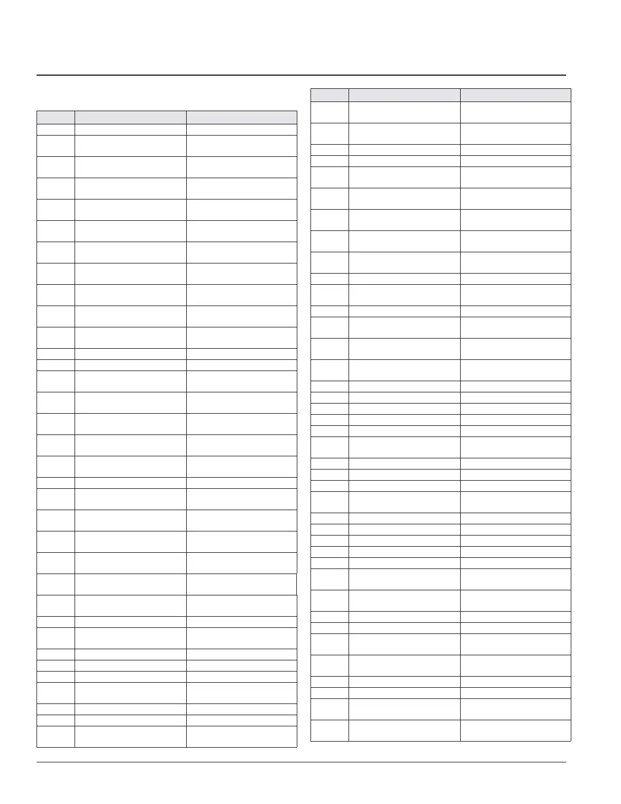
Wiring Diagrams: Legend
Wiring Diagrams
Legend
ID Description Standard location
ACT3, 4 Actuator motor, economizer Economizer section
ACT5 Actuator motor, discharge
isolation damper
Discharge section
ACT6 Actuator motor, return air
isolation damper
Return section
ACT7 Actuator motor, heat face/
bypass
Coil section, heat
ACT8 Actuator motor, cool face/
Bypass
Coil section, cool
ACT10,
11
Actuator motor, exhaust
dampers
Return section
ACT12 Actuator motor, enthalpy wheel
bypass damper
Energy recovery section
AFD10 Adjustable frequency drive,
supply fan
AFD/supply fan section
AFD11 Adjustable frequency drive,
evap cond. fans
Main/RCE control box
AFD20 Adjustable frequency drive,
return/exhaust fan
AFD/ret. ex. fan section
AFD60 Adjust. freq. drive, energy
recovery wheel(s)
Energy recovery section
AS Airflow switch, burner blower Gas heat box
BM Burner blower motor Heat section, gas
C1–8 Power factor capacitors,
compressors
Condenser section
C10 Power factor capacitors,
supply fan
Supply Fan section
C11 Capacitors, Speedtrol, circuit
#1
Condenser bulkhead
C20 Power factor capacitors, return
fan
Return section
C21 Capacitors, Speedtrol, circuit
#2
Condenser bulkhead
CB10 Circuit breaker, supply fan Main control box
CB11 Circuit breaker, evaporative
condenser fan(s)
Main/cond. control box
CB20 Circuit breaker, return/ exhaust
fan
Main control box
CB60 Circuit breaker, energy
recovery wheel
Main control box
CCB1, 2 Compressor control boards,
refrig. circuits
Main control box
CPC Circuit board, main, micro
controller
Main control box
CPR Circuit board, expansion, micro
controller
Main control box
CS1, 2 Control switches, refrig. circuits Main/cond. control box
DAT Discharge air temperature
sensor
Discharge section
DFLH Design flow lefthand sensor Return section
DFRH Design flow righthand sensor Return section
DHL Duct hi-limit Main control box
DS1 Disconnect, total unit or cond/
heat
Main control box
DS2 Disconnect, SAF/RAF/controls Main control box
DS3 Disconnect, electric heat Electric heat box
DS4 Disconnect, condenser (RCS
Only)
RCS control box
EAT Exhaust air temperature
sensor
Energy recovery section
EFT Entering fan air temperature
sensor
Supply fan section
EHB1 Staged electric heat board Main control box
ERB1 Energy recovery board Main control box
ERM1 Energy recovery wheel motor
#1
Energy recovery section
ERM2 Energy recovery wheel motor
#2
Energy recovery section
F1A, B Fuse, control circuit
transformer (T1), primary
Main control box
F1C Fuse, control circuit
transformer (T1), secondary
Main control box
F2 Fuse, control circuit
transformer (T2), primary
Main control box
F3 Fuse, burner blower motor Main control box
F4 Fuse, ctrl. circuit transformer
(T4), primary
Main control box
FB11, 12 Fuseblock, Speedtrol Main/cond. control box
FB31–40 Fuseblock, electric heat (top
bank)
Electric heat box
FB41–50 Fuseblock, electric heat (bot.
bank)
Electric heat box
FB65 Fuseblock, evap. cond. sump
heater
Main/cond. control box
FD Flame detector Heat section, gas
FLC Fan limit control Heat section, gas
FP1, 2 Frost protection, refrig. circuits Coil section, cool
FS1, 2 Freezestat control Coil section, heat/cool
FSG Flame safeguard Gas heat box
GCB1 Generic condenser board,
refrig. circ.
Main control box
GFR1, 2 Ground fault relay Main control box
GFS1, 2 Ground fault sensor Main control box
GFR4 Ground fault relay, condenser Condenser control box
GFS4 Ground fault sensor,
condenser
Condenser control box
GRD Ground All control boxes
GV1 Gas valve, pilot Heat section, gas
GV2 Gas valve, main/safety Heat section, gas
GV3 Gas valve, redundant/safety Heat section, gas
GV4–8 Gas valve, main, hi turn down Heat section, gas
HL1–10 Hi-limits, pwr, elec heaters (top
bank)
Heat section, electric
HL11–20 Hi-limits, pwr, elec heaters
(bot. bank)
Heat section, electric
HL22 Hi-limits, gas heat (pre-filters) Supply fan section
HL23 Hi-limits, gas heat (final filters) Final filter section
HL31–40 Hi-limits, ctl. elec heaters (top
bank)
Heat section, electric
HL41–50 Hi-limits, ctl. elec heaters (bot.
bank)
Heat section, electric
HP1–4 Hi-pressure controls, refrig On compressors
HP5 Hi-pressure controls, gas Heat section, gas
HS1 Heat switch, electric heat
shutdown
Main control box
HS3 Heat switch, electric heat
deadfront interlock
Electric heat box
ID Description Standard location