IM 738-2 47
Mechanical Installation: Damper Assemblies
Damper Assemblies
The optional damper assemblies described in this section
normally are ordered with factory-installed actuators and
linkages. The following sections describe operation and
linkage adjustment of the factory option.
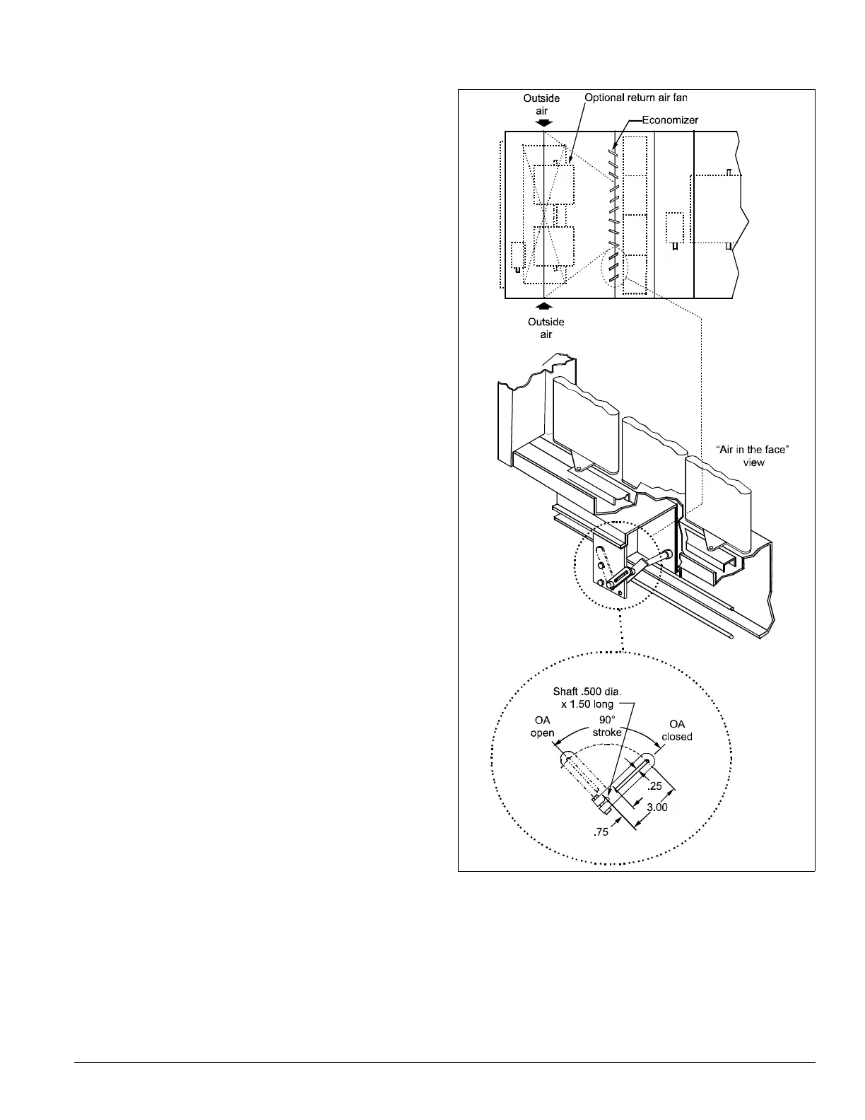
Economizer Dampers
Outside air intake is provided on both sides of the unit, and the
return
air path is at the center of the damper set. As the single
actuator modulates the outside air dampers open, the return air
dampers close. Exhaust air exits the unit through the gravity
relief dampers provided at the end of the economizer section.
The damper is set so that the crankarm
moves through a 90-
degree angle to bring the economizer dampers from full open
to full close (see Figure 57). Access to the actuator and linkage
is from the filler section. Mechanical s
tops are placed in the
crankarm mounting bracket. Do not remove stops. Driving the
crankarm past the stops results in damage to the linkage or
damper. The unit ships with a shipping bolt securing the
linkage crankarm. Remove shipping bolt before use.
Figure 57. Damper adjustment
Note: For good airflow control, adjust linkages so damper
blades do not open beyond 70 degrees. Opening a
damper blade beyond 70 degrees has little effect on its
airflow.
Do not “overclose” low leak damper blades. The edge
seal sh
ould just lightly contact the adjoining blade. The
blades will lock up if they are closed so far the seal goes
over center.