IM 893-10 • ROOFPAK SINGLEZONE UNITS 100 www.DaikinApplied.com
unIT oPTIons
Oil Injection Control
The VFD compressor contains an oil injection valve and
solenoid (SV11) as standard. The oil injection valve provides
lubrication to the scroll set under low speed/low refrigerant
velocity situations. The oil injection valve is a normally closed
valve. Below 50 rps (100 Hz) the valve is closed and directs oil
to the scroll set suction port. Above 50 rps (100 Hz) the solenoid
is bypassed and sends oil into sump. The oil injection valve/
solenoid is mounted directly on the compressor and is controlled
by the Compressor VFD (relay 1 output, terminals NO & Com).
The coil voltage for the oil injection solenoid is 24 Vac.
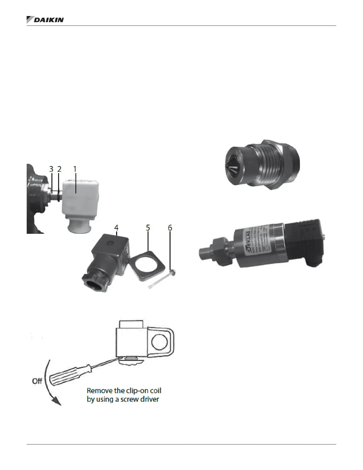
The coil can be removed if required by carefully prying off
the valve stem. The wiring connector is attached to the coil
by a screw in the center of the housing. Refer to Figure 104
and Figure 105.
Figure 104: Assembly Components
Figure 105: Oil Injection Control Dismanteling
Optical Oil Level Sensor
An optical oil sensor is used to monitor oil level in VFD
compressor sump. The sensor is mounted directly to a tting
on the VFD compressor shell and can be removed without
having to depressurize/reclaim the refrigeration system.
Optical oil indication signal is sent to MTIII Expansion Module
‘C’ (terminals X3 & M). Normal oil indication will provide a
contact closure from relay R40. Relay R40 will de-energize
during low oil indication, removing signal to terminal X3 and
will start the unit in an oil boost sequence. Refer to Figure
106 and Figure 107
Figure 106: Sightglass for Optical Oil Sensor/Switch
Figure 107: Optical Oil Level Sensor/Switch
Electrical Connections and Wiring
Basic Connections
Depending on the frequency converter version, the physical
position of individual connectors may differ. Always make sure
that the compressor terminals, U, V and W are connected to
the frequency converter terminals, 96, 97 and 98 respectively.
The compressor motor cable is shielded and the armoured
part of the cable is connected to a ground on both cable ends;
at the side of the compressor and at the side of the frequency
converter.

 Loading...


