IM 893-10 • ROOFPAK SINGLEZONE UNITS 40 www.DaikinApplied.com
MeChanICal InsTallaTIon
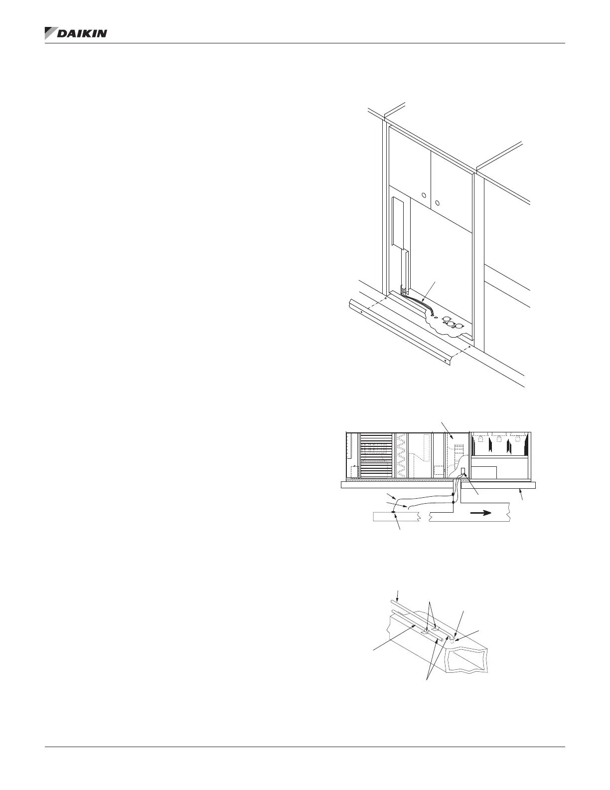
Installing Duct Static Pressure Sensor Taps
For all VAV units, duct static pressure taps must be eld
installed and connected to the pressure sensors in the unit.
Sensor SPS1 is standard; additional sensor SPS2 is optional.
These sensors are located in the main control panel (see
Control Panel on page 8).
Carefully locate and install the duct static pressure sensing
tap. Improperly locating or installing the sensing tap causes
unsatisfactory operation of the entire variable air volume
system. Below are pressure tap location and installation
recommendations. The installation must comply with local code
requirements
1. Install a tee tting with a leak-tight removable cap in each
tube near the sensor tting. This facilitates connecting a
manometer or pressure gauge if testing is required.
2. Use different colored tubing for the duct pressure (HI)
and reference pressure (LO) taps, or tag the tubes.
Daikin recommends 3/16ʺ I.D. plastic tubing.
3. Locate the duct pressure (HI) tap near the end of a long
duct to ensure that all terminal box take-offs along the
run have adequate static pressure.
4. Locate the duct tap in a non-turbulent ow area of the
duct. Keep it several duct diameters away from take-off
points, bends, neckdowns, attenuators, vanes, or other
irregularities.
5. Use a static pressure tip (Dwyer A302 or equivalent) or
the bare end of the plastic tubing for the duct tap. (If the
duct is lined inside, use a static pressure tip device.)
6. Install the duct tap so that it senses only static pressure
(not velocity pressure). If a bare tube end is used,
it must be smooth, square (not cut at an angle) and
perpendicular to the airstream (see Figure 46).
7. Locate the reference pressure (LO) tap somewhere near
the duct pressure tap within the building (see Figure
45). If the reference tap is not connected to the sensor,
unsatisfactory operation will result.
8. Route the tubes between the curb and the supply duct,
and feed them into the unit through the knockout in the
bottom of the control panel (see Figure 45). Connect the
tubes to appropriate barbed ttings in the control panel.
(Fittings are sized to accept 3/16ʺ I.D. plastic tubing.)
Figure 45: Static Pressure Tubing Entrance Location
Figure 46: Pressure Sensing Tubing Installation
Static pressure
tubing
Main Control Panel
"HI line"
"LO" line
Remote Sense Point
Roof
SPS1
Rubber
Grommet
Ductwork
(Remote Location)
To Sensor
"HI" input
Tubing Extends
thru Approx. 1/8"
To Sensor
"LO" Input
Pressure Sensing
Tubing
Tube
Clamps

 Loading...


