WIrIng dIagraMs
www.DaikinApplied.com 63 IM 893-10 • ROOFPAK SINGLEZONE UNITS
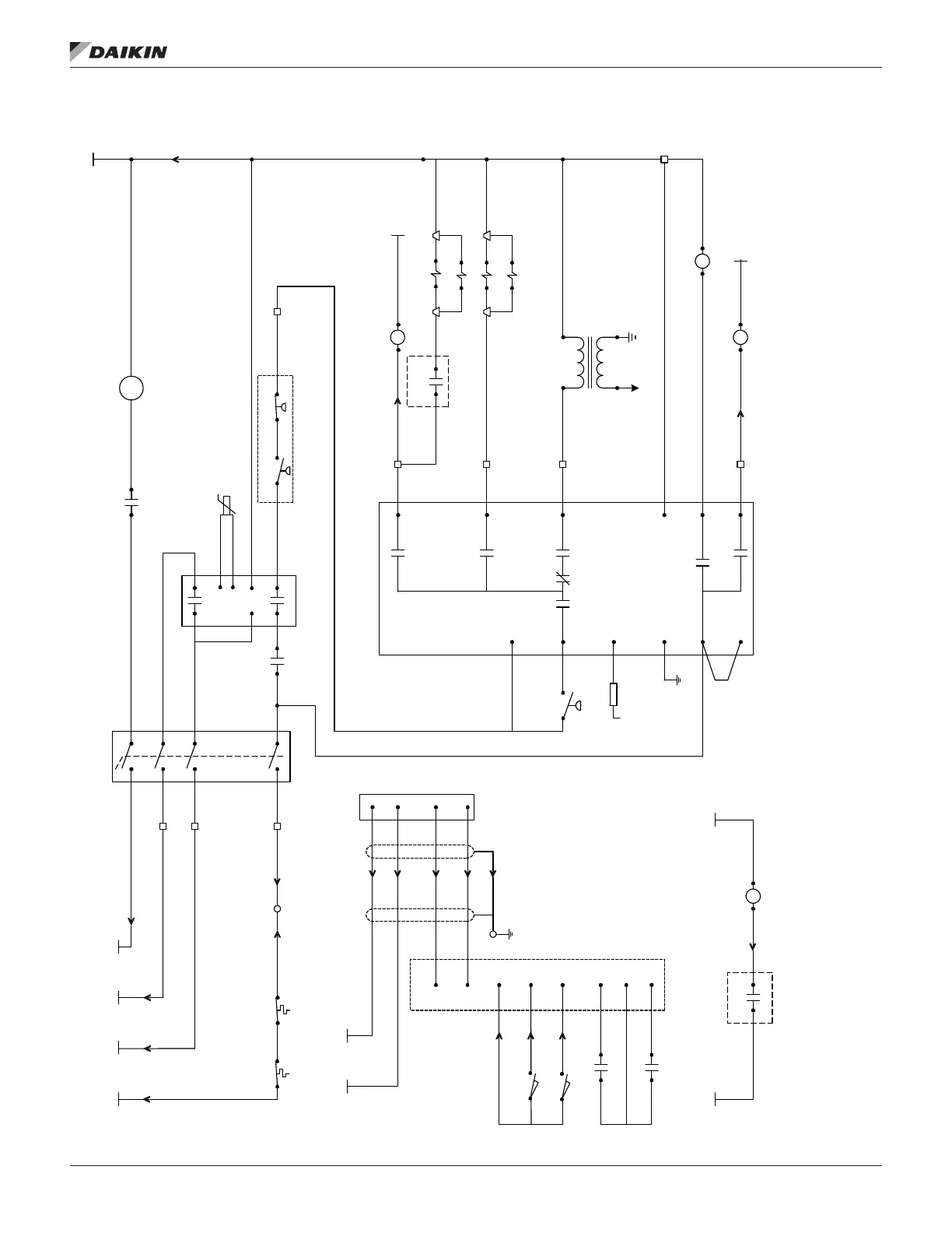
Figure 66: HTD Gas Burner Schematic
T1 _N
6000 V
IT
115VAC
R2 2
5 (L1)
4
302
F
L2G
3k1
6k1
FD
FS G
8
6
9
017
4k1
2k2
1K1 1K2 1K5
CO M NO
AS
R2 0
2 1
4 5
8 7
11
10
S3
T2_115 VAC/
268
HL22
SIG_ 1/ 427
PL19
1
PL 16
1
PL16
2
PL19
3
TB 3_174
10
PL 19
2
5 9
1
3
5
13 14
PL19
4
NB
R2 4
T1_N/ 16 8
PL19_5
13 14
S1 _1/201
M29
2 4
M29
1 3
GV4A
GV4B
GV1A
8
9
BM
4
6
SIG_ 2/ 427
PL 18
6
T1 N/ 16 8
LP5
R W
HP5
R B
optional
T3 T2
CO M NO
FA N
LI MIT
FL C
T7
T8
CO M NO
X7
EXP B
M
X2
X3
X1
T3_24 VAC
M
R2 2
5 9
GR D
PL18
3
M
X4
R2 4
5 9
PL18
4
PL18
5
+
VM1
-
T2
T1
T3 _N
R2 0
13 14
DO1
203E
C1 DO 1
T2_115 VAC/
268
T1_N/ 168
EXP B
168A
PL18_8
HL23
PL19
9
1 2 1 2
LS 1
LS 2
PL 19
6
PL 19
7
PL19
8
CO M NO
CO M NO
DO2
EXP B
GV1B
PL18
2
PL18
1
temp sensor
Typical Sequence of Operation
When 120V power is furnished through the system on/off switch (S1), through the burner on/off switch (S3), and through the high limit control (FLC), terminal #6 on the flame
safeguard (FSG) is po wered on a call for heat. Whenever power is restored to the flame safeguard, the flame safeguard will go
through a 10 second initiation period before the
prepurge period will begin. The burner air control valve will be at minimum position during off cycles. Upon a call for heat or any other time that a prepurge cycle will occur, the

 Loading...


