IM 893-10 • ROOFPAK SINGLEZONE UNITS 64 www.DaikinApplied.com
WIrIng dIagraMs
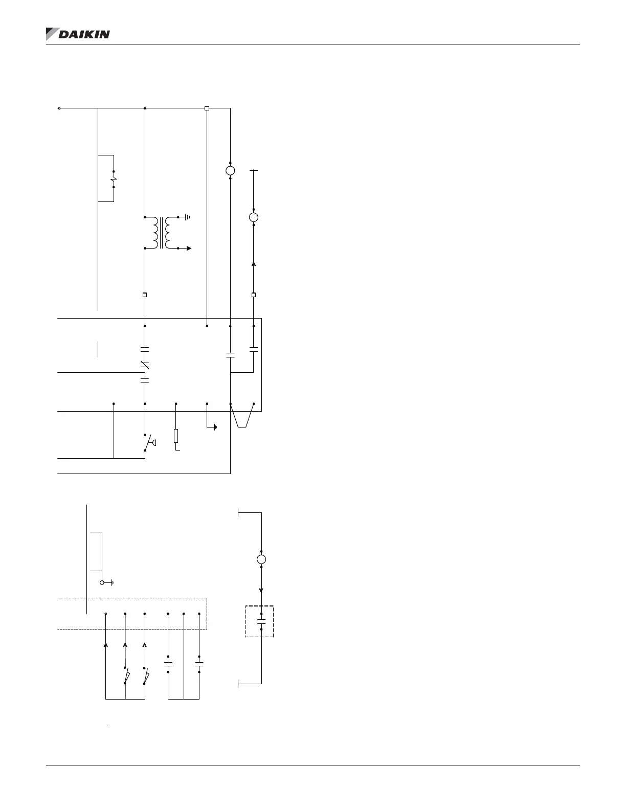
Figure 66 continued: HTD Gas Burner Schematic
6000 V
IT
115VAC
5 (L1)
4
302
F
L2G
3k1
6k1
FD
6
17 0
1K1 1K2 1K5
CO M NO
AS
NB
R2 4
T1_N/ 16 8
PL19_5
13 14
M29
1 3
GV4B
4
6
X2
X3
X1
R2 2
5 9
GR D
M
X4
R2 4
5 9
R2 0
13 14
DO1
203E
C1 DO 1
T2_115 VAC /
268
T1_N/ 168
EXP B
168A
PL18_8
LS1
LS2
6
PL 19
7
PL19
8
CO M NO
CO M NO
Typical Sequence of Operation
When 120V power is furnished through the system
ON/OFF switch (S1), through the burner ON/OFF switch (S3), and through the high limit control (FLC), terminal #6 on the flame
safeguard (FSG) is powered on a call for heat. Whenever power is restored to the flame safeguard, the flame safeguard will go t
hrough a 10 second initiation period before the
prepurge period will begin. The burner air control valve will be at minimum position during off cycles. Upon a call for heat or any other time that a prepurge cycle will occur, the
air control valve will be repositioned to the maximum position for the prepurge and then returned to the minimum position for l
ow fire start.
Upon a call for heat, the controller will close (EMB-DO1) energizing R20, closing it’s N/O contact and energize terminal # 6 on the FSG. The FSG then energizes its terminal #4,
which powers the burner combustion air blower motor (BM) and starts the prepurge cycle. The call for heat will al so initiate the controller to reposition the burner air valve to its
maximum open position for prepurge. Whent he actuator reaches the full open positino, switch (LS2) is 'made' which will provide
a digital input to thec ontroller (EMB-DIX3).
This digital input will initiate a 20 second (adjustable) timing period in the controller. At the completion of the timing period, the controller will signal the actuator to drive to its
minimum (low fire) position. At the completion of the FSG prepurge cycle the valve will be at the minimum open position and the minimum position switch (LS1) will be 'made',
providing a digital input to the controller (EMB-DIX2). When the burner air valve is at it minimum position and the low positio
n switch (LS1) is made, the controller will close
the digital output (EMB-DO2) allowing the combination gas valve(s) (GV1) to be energized upon completion of the FSG prepurge
cycle.
After completion of the FSG prepurge period there will be a 10 second trial for ignition during which terminal #8 (combination
gas valve - GV1) and terminal #10 (ignition
transformer - IT) will be energized. If flame is being detected through the flame rod (FD) at the completion of the 10 second t
rial for ignition period, terminal #10 (ignition
transformer - IT) will be de-energized and terminal #9 (main gas valves - GV4) will be energized and the control system will be
allowed to control the firing rate once the heating
stage timer (default 5 minutes) has passed. After the flame has lit and been proven and the heating stage time has passed, the controller will modulate (VM1), to the required firing
rate. In the event the flame fails to ignite or the flame safeguard fails to detect its flame within 10 seconds, terminals #4,
8, 9, and 10 will be de-energized, thus de-energizing the
burner. The FSG would then lockout and would require manual resetting. If the FSG goes into lockoput, terminal 3 on the FSG will be energized and will energize R24, providing
a digital input to the controller (EMB-DIX2) If an attempt is made to restart the burner by resetting the FSG or if an automati
c restart is initiated after flame failure the earlier
described prepurge cycle with the wide open air valve will be repeated. If the unit overheats, the high limit control (FLC) wil
l cycle the burner, limiting furnace temperature to the
limit control set point. The flame safeguard contains 'LEDS' (lower left corner) that will glow to indicate operation .

 Loading...


