Do you have a question about the Daikin REYQ96 and is the answer not in the manual?
Lists the model names for indoor and outdoor units.
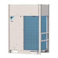
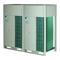
Details the visual appearance of indoor and outdoor units.
Provides guidance on selecting the correct model based on capacity and configuration.
Lists detailed technical specifications for various components and systems.
Technical specifications for outdoor units, including cooling/heating capacity, dimensions, and components.
Technical specifications for various types of indoor units.
Technical specifications for BS Units, including connection range and capacity.
Overview of the refrigerant circuit design and components.
Refrigerant circuit details for specific outdoor unit models.
Diagrams showing the layout of functional parts within the units.
Diagrams illustrating refrigerant flow under different operating conditions.
General overview of system functions and operational modes.
Explanation of fundamental control mechanisms and operations.
Explanation of special control functions like startup and oil return.
System protection mechanisms against abnormal conditions.
Additional control functions beyond basic and special controls.
Overview of control logic for indoor units.
Procedures for conducting initial test operations after installation.
Diagram and explanation of the outdoor unit's PC board components.
Configuring settings for the system based on installation conditions.
Methods for troubleshooting using the remote controller.
Troubleshooting based on error codes displayed on the remote controller.
Troubleshooting steps for "A0" error code related to external protection.
Troubleshooting steps for "A1" error code indicating PC board failure.
Troubleshooting steps for "A3" error code related to drain level control.
Troubleshooting steps for "A6" error code indicating fan motor issues.
Troubleshooting steps for "A7" error code related to swing flap motor.
Troubleshooting for "A9" error code regarding electronic expansion valve.
Troubleshooting for "AF" error code indicating high drain level.
Troubleshooting for "AJ" error code related to capacity determination.
Troubleshooting for "C4" error code related to heat exchanger thermistor.
Troubleshooting for "C5" error code related to gas pipe thermistor.
Troubleshooting for "C9" error code related to suction air thermistor.
Troubleshooting for "CJ" error code related to remote controller thermostat.
Troubleshooting for "E1" error code indicating outdoor PC board defect.
Troubleshooting for "E3" error code related to high pressure switch.
Troubleshooting for "E4" error code related to low pressure sensor.
Troubleshooting for "E5" error code indicating INV compressor lock.
Troubleshooting for "E6" error code indicating STD compressor issues.
Troubleshooting for "E7" error code related to outdoor fan motor.
Troubleshooting for "E9" error code regarding electronic expansion valve.
Troubleshooting for "F3" error code indicating abnormal discharge pipe temperature.
Troubleshooting for "F6" error code indicating refrigerant overcharge.
Troubleshooting for "H7" error code related to outdoor fan motor signal.
Troubleshooting for "H9" error code related to outdoor air thermistor.
Troubleshooting for "J2" error code indicating current sensor malfunction.
Troubleshooting for "J3" error code related to discharge pipe thermistor.
Troubleshooting for "J4" error code related to heat exchanger gas pipe thermistor.
Troubleshooting for "J5" error code related to suction pipe thermistor.
Troubleshooting for "J6" error code related to heat exchanger thermistor.
Troubleshooting for "J7" error code related to receiver outlet liquid pipe thermistor.
Troubleshooting for "J8" error code related to oil equalizing pipe thermistor.
Troubleshooting for "J9" error code related to sub-cooling heat exchanger gas pipe thermistor.
Troubleshooting for "JA" error code related to discharge pipe pressure sensor.
Troubleshooting for "JC" error code related to suction pipe pressure sensor.
Troubleshooting for "L4" error code related to inverter radiating fin temperature.
Troubleshooting for "L5" error code indicating inverter compressor abnormality.
Troubleshooting for "L8" error code indicating abnormal inverter current.
Troubleshooting for "L9" error code indicating inverter startup error.
Troubleshooting for "LC" error code related to communication between inverter and control PC board.
Troubleshooting for "P1" error code related to inverter over-ripple protection.
Troubleshooting for "P4" error code related to inverter radiating fin temperature sensor.
Troubleshooting for "PJ" error code related to faulty field setting or PC board combination.
Troubleshooting for "U0" error code related to low pressure or expansion valve failure.
Troubleshooting for "U1" error code related to power phase issues.
Troubleshooting for "U2" error code related to power supply issues.
Troubleshooting for "U3" error code indicating check operation was not performed.
Troubleshooting for "U4" error code related to indoor unit transmission.
Troubleshooting for "U5" error code related to remote controller and indoor unit transmission.
Troubleshooting for "U7" error code related to transmission between outdoor units.
Troubleshooting for "U8" error code related to transmission between main and sub remote controllers.
Troubleshooting for "U9" error code related to transmission within the same system.
Troubleshooting for "UA" error code related to improper unit combinations.
Troubleshooting for "UC" error code related to address duplication in centralized control.
Troubleshooting for "UE" error code related to transmission between centralized controller and indoor unit.
Troubleshooting for "UF" error code indicating the system is not set.
Troubleshooting for "UH" error code related to undefined refrigerant system address.
Troubleshooting steps specific to central remote controller operations.
Troubleshooting for "M1" error code indicating a PC board defect.
Troubleshooting for "M8" error code related to transmission between optional controllers.
Troubleshooting for "MA" error code related to improper combination of optional controllers.
Troubleshooting for "MC" error code related to address duplication or improper settings.
Troubleshooting steps specific to schedule timer operations.
Troubleshooting for "UE" error code related to transmission between centralized controller and indoor unit.
Troubleshooting for "M1" error code indicating PC board defect in schedule timer.
Troubleshooting for "M8" error code related to transmission between optional controllers for centralized control.
Troubleshooting for "MA" error code related to improper combination of optional controllers.
Troubleshooting for "MC" error code related to address duplication or improper settings in schedule timer.
Troubleshooting steps specific to unified ON/OFF controller operations.
Troubleshooting steps when the operation lamp blinks on the unified controller.
Troubleshooting for single blink of "Under Centralized Control" display.
Troubleshooting for double blink of "Under Centralized Control" display.
Step-by-step instructions for replacing the INV compressor.
Detailed procedure for replacing the INV compressor.
Visual representations of refrigerant piping for different system components.
Electrical wiring diagrams for system components.
Comprehensive list of electrical and functional parts used in the system.
Details available optional accessories and their compatibility.
Illustrates connection examples for the R-410A refrigerant system.
Data relating thermistor resistance to temperature for diagnostics.
Information on pressure sensors used in the system.
Procedure for replacing inverter power transistors and diode modules.
Important precautions when handling the new R-410A refrigerant.
General overview and characteristics of R-410A refrigerant.
List of required tools and devices for working with R-410A.
| Brand | Daikin |
|---|---|
| Model | REYQ96 |
| Category | Air Conditioner |
| Language | English |