7 | Installation
Installer reference guide
60
RZAG71~140N
Sky Air Alpha-series
4P695307-1A – 2024.02
7.7.5 Specifications of standard wiring components
Component V1 Y1
71 100 125~140 71 100 125 140
Power supply
cable
MCA
(a)
18.8A 23.3A 28.8A 12.3A 15.4A 15.7A 15.4A
Voltage range 220~240V 380~415V
Phase 1~ 3N~
Frequency 50Hz
Wire sizes Must comply with applicable legislation
Interconnection cables Minimum cable section of 2.5 mm² and applicable for 230 V
Recommended field fuse 20A 32A 16A
Earth leakage circuit breaker Must comply with applicable legislation
(a)
MCA=Minimum circuit ampacity. Stated values are maximum values (see electrical data of combination with indoor units for exact
values).
7.7.6 To connect the electrical wiring to the outdoor unit
NOTICE
▪ Follow the wiring diagram (delivered with the unit, located at the inside of the
service cover).
▪ Make sure the electrical wiring does NOT obstruct proper reattachment of the
service cover.
1 Remove the service cover. See "7.2.2To open the outdoor unit"[434].
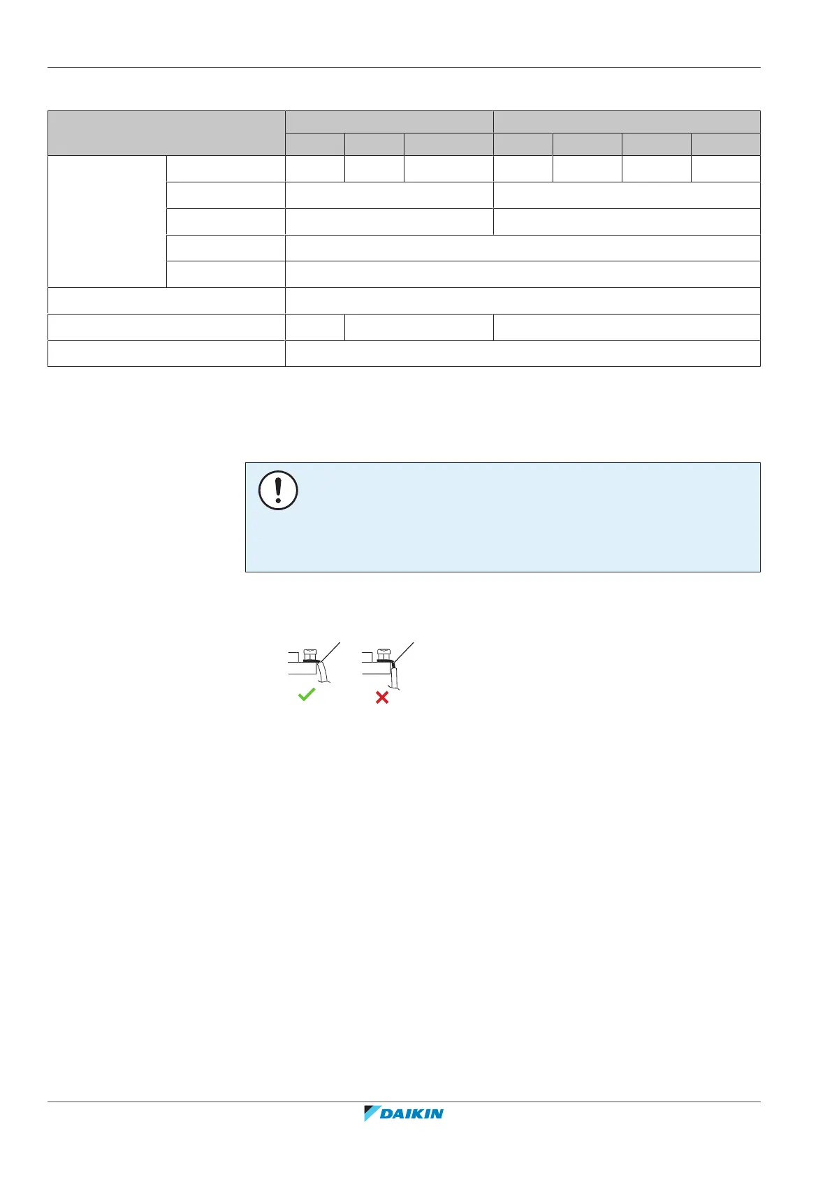
2 Strip insulation (20mm) from the wires.
a Strip wire end to this point
b An excessive strip length may cause electrical shock or leakage
3 Connect the interconnection cables and power supply as follows:
 Loading...