13 | Technical data
Installer reference guide
79
RZAG71~140N
Sky Air Alpha-series
4P695307-1A – 2024.02
A1
A2
≥500
≥1000
A2
≥500
≥300
≥
100
(1)
≥
100
(1)
B1
A2
B2
≥100
≥300
B2
≥100
≥1000
B2
≥
100
(1)
≥
100
(1)
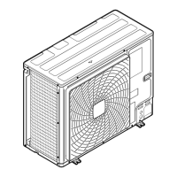
(1) For better serviceability, use a distance ≥250mm
A1=>A2 (A1) If there is danger of drainage dripping and freezing between the upper and lower units…
(A2) Then install a roof between the upper and lower units. Install the upper unit high enough above the lower unit to
prevent ice buildup at the upper unit's bottom plate.
B1=>B2 (B1) If there is no danger of drainage dripping and freezing between the upper and lower units…
(B2) Then it is not required to install a roof, but seal the gap between the upper and lower units to prevent discharged air
from flowing back to the suction side through the bottom of the unit.
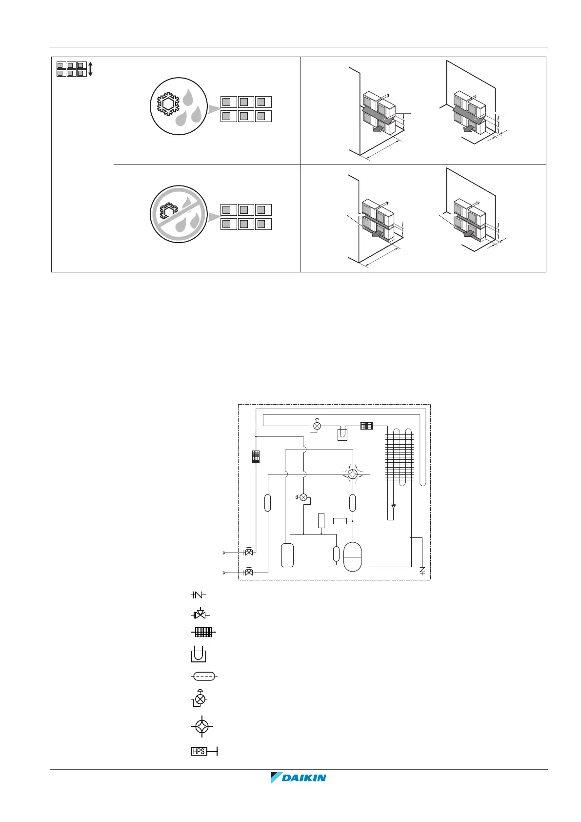
13.3 Piping diagram: Outdoor unit
Service port (with 5/16" flare)
Stop valve
Filter
PCB cooling
Muffler
Electronic expansion valve
4‑way valve
High pressure switch
 Loading...