IOM 1207-6 • TRAILBLAZER
®
MODEL AGZ CHILLERS 14 www.DaikinApplied.com
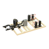
Figure 21: Typical Piping, Brazed-Plate Evaporator
Chilled Water Piping
All evaporators and condensers have OGS-type grooved water
connections (adhering to Standard AWWA C606). The installing
contractor must provide matching mechanical connections.
Be sure that water inlet and outlet connections match certied
drawings and nozzle markings. PVC piping should not be
used.
WARNING
Polyolester Oil, commonly known as POE oil is a synthetic
oil used in many refrigeration systems, and is present in this
Daikin product. POE oil, if ever in contact with PVC/CPVC, will
coat the inside wall of PVC/CPVC pipe causing environmental
stress fractures. Although there is no PVC/CPVC piping in
this product, please keep this in mind when selecting piping
materials for your application, as system failure and property
damage could result. Refer to the pipe manufacturer’s
recommendations to determine suitable applications of the
pipe.
CAUTION
To prevent damage to the evaporator and potential chiller
failure, a supply strainer is required in the inlet water piping
which connects to this evaporator. This strainer must be
installed prior to operation of the chilled liquid pumps.
Field installed water piping to the chiller must include:
• A cleanable strainer installed at the water inlet to the
evaporator to remove debris and impurities before they
reach the evaporator. Install cleanable strainer within
5 feet (1500 mm) of pipe length from the evaporator
inlet connection and downstream of any welded
connections (no welded connections between strainer
and evaporator).
• AGZ-E models 030-241 require a strainer with
perforations no larger than 0.063” (1.6 mm) diameter. See
the “Inlet Strainer Guidelines” for more information.
• A water ow switch must be installed in the horizontal
piping of the supply (evaporator outlet) water line to avoid
evaporator freeze-up under low or no ow conditions. The
ow switch may be ordered as a factory-installed option,
a eld-installed kit, or may be supplied and installed in the
eld. See page 16 for more information.
NOTE: Units with the optional pump package include
the strainer and ow switch. See page 42 for
pump package components.
• Piping for units with brazed-plate evaporators must have
a drain and vent connection provided in the bottom of
the lower connection pipe and to the top of the upper
connection pipe respectively, see Figure 21. These
evaporators do not have drain or vent connections due
to their construction. Purge air from the water system
before unit start-up to provide adequate ow through the
evaporator.
• Adequate piping support, independent from the unit,
to eliminate weight and strain on the ttings and
connections.
It is recommended that the eld installed water piping to the
chiller include:
• Thermometers at the inlet and outlet connections of the
evaporator.
• Water pressure gauge connection taps and gauges at
the inlet and outlet connections of the evaporator for
measuring water pressure drop.
• Shuto valves are necessary to isolate the unit from the
piping during unit servicing.
• Minimum bends and changes in elevation to minimize
pressure drop.
• An expansion tank or regulating and relief valve to
maintain adequate water pressure
• Vibration eliminators in both the supply and return water
lines to reduce transmissions to the building.
• Flush the system water piping thoroughly before making
connections to the unit evaporator.
• Piping insulation, including a vapor barrier, helps prevent
condensation and reduces heat loss.
• Regular water analysis and chemical water treatment
for the evaporator loop is recommended immediately at
equipment start-up.
NOTE: Failure to follow these measures may result in
performance and reliability issues.
Air
Vent
Flow
Switch
Vibration
Eliminators
Drain
Outlet
Inlet
P
Isolation
Valves
Strainer
WELDED PIPE CONNECTIONS ARE NOT ALLOWED
BETWEEN THE STRAINER AND EVAPORATOR DUE
TO THE CHANCE OF SLAG ENTERING THE EVAPORATOR
 Loading...