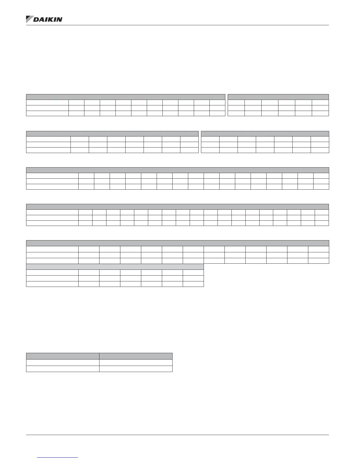
Operating Limits
Do not exceed the operating limits in Table 17 through Table
21. A fan wheel operated beyond the rpm and temperature
limits shown can suffer permanent distortion or fracture. The
resulting unbalance can cause severe unit vibration.
Table 17: Fan Operating Limits—Unit Sizes 003 to 035
Forward Curved—Housed Airfoil—Housed
Diameter 9×4 9×7 9×9 10.62 12.62 15 18 20 22.25 24.50 13.22 14.56 16.19 19.69 21.56 24.00
Max. RPM Class I N/A 2189 2223 1934 1614 1328 1155 1050 944 858 3000 3000 2300 2000 1700 1500
Max. RPM Class Il 2244 2854 2896 2518 2091 1725 1450 1200 1030 910 4335 3918 3457 2858 2427 2255
Table 18: Fan Operating Limits—Unit Sizes 040–090
Forward Curved—Housed Airfoil—Housed
Diameter 20 22.38 25 27.62 30.25 33 36 20 22.25 24.5 27 30 33 36.5
Max. RPM Class I 1010 930 790 690 650 600 560 2077 1875 1691 1479 1328 1209 1073
Max. RPM Class Il 1281 1178 1011 910 835 763 715 2703 2413 2199 1928 1730 1579 1401
Table 19: Fan Operating Limits—Belt-Drive Plenum Fans
Belt-Drive Plenum fans
Size 13 15 16 18 20 22 24 27 30 33 36 40 44 49 54 60
Max. RPM Class II 3909 3468 2820 2930 2674 2403 2183 1860 1783 1620 1465 1329 1202 1091 986 891
Max. RPM Class IlI 4000 4000 3887 3735 3409 3065 2780 2423 2182 1984 1759 1598 1447 1314 1178 1071
Table 20: Fan Operating Limits—Direct-Drive Plenum Fans
Direct-Drive Plenum Fans
Size 11 12 13 15 16 18 20 22 24 27 30 33 36 40 44 49 54 60
Max. RPM Class II 4000 4000 — 3909 3650 3650 2674 2403 2183 1981 1783 1620 1465 1329 1202 — — —
Max. RPM Class IlI — — 4000 4000 3887 3735 3409 3065 2780 2423 2182 1984 1759 1598 1447 1314 1178 1071
Table 21: Fan Operating Limits—Inline Fans, Twin Fans
Inline Fans/Twin Fans
Diameter 18.25 20 22.25 24.5 27 30 33 36.5 40.25 44.50 49 54.25
Max. RPM Class I 2727 2488 2236 2041 1835 1665 1476 1330 1208 1072 973 880
Max. RPM Class II 3409 3111 2796 2551 2294 2082 1846 1662 1510 1340 1216 1100
Twin Fans
Diameter 9×9 10.62 12.62 15 18.12 20
Max. RPM 2575 2400 2000 1700 1400 1200
Max. HP 10 15 15 30 40 40
Fan Vibration Levels
Each unit as shipped is trim balanced to operate smoothly. To
provide satisfactory operation after shipping and installation,
use the accepted industry guidelines for eld balancing fans.
See Table 22.
Table 22: Vibration Levels
Fan Speed (RPM) Vibration
800 or less 5 mils maximum displacement
801 or greater 0.20 in/sec. maximum velocity
Note:
Excessive vibration from any cause contributes to premature fan and motor
bearing failure. Monitor overall vibration levels every six months of operation.
An increase in levels is an indication of potential trouble.
Vibration Causes
1. Wheel imbalance.
a. Dirt or debris on wheel blades.
b. Loose set screws in wheel hub or bearing-to-shaft.
c. Wheel distorted from overspeed.
2. Bent shaft.
3. Drive faulty.
a. Variable pitch sheaves—axial and radial runout of
anges; uneven groove spacing; out of balance.
Also similar faults in driven sheave.
b. Bad V-belts; lumpy, or mismatched; belt tension
too tight or too loose.
4. Bad bearings, loose bearing hold-down bolts.
5. Motor imbalance.
6. Fan section not supported evenly on foundation.
IM 672-11 • VISION AIR HANDLING UNIT 36 www.DaikinApplied.com
operaTIon
 Loading...