IM 915-13 • VISION - EXTENDED SIZES 30 www.DaikinApplied.com
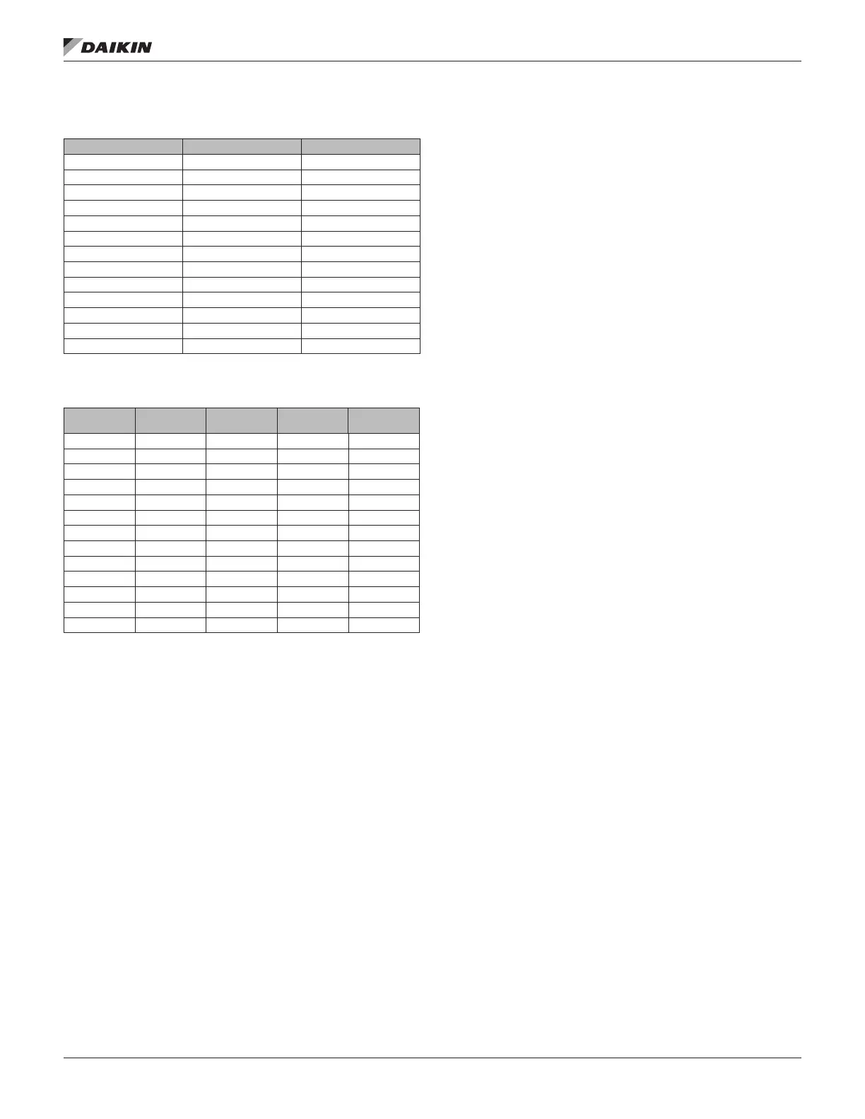
Table 15: DDPL Factors for Free and Ducted Inlet –
Non-Standard Density Method, Daikin Applied Piezo Ring
12 783.66 792.43
15 767.48 763.62
16 732.77 757.40
18 612.29 619.65
20 653.83 652.65
22 674.42 673.16
24 679.53 681.34
27 656.57 660.15
30 691.07 692.12
33 675.26 677.89
36 675.83 676.67
40 699.51 694.22
44 681.07 681.01
Table 16: DDPL Factors for Free and Ducted Inlet –
Standard Density Method, Daikin Applied Piezo Ring
Free Inlet F
Ducted
Inlet F
Area A
Wheel
Diameter
12 1004.66 1016.46 0.344 12.40
15 1261.99 1260.20 0.439 14.00
16 1526.96 1572.35 0.552 15.75
18 1675.69 1672.77 0.721 18.25
20 2117.33 2110.61 0.865 20.00
22 2710.75 2693.35 1.074 22.25
24 3312.67 3319.41 1.300 24.50
27 3901.60 3929.94 1.582 27.00
30 5017.64 5033.71 1.957 30.00
33 5942.72 5979.46 2.362 33.00
36 7274.52 7316.07 2.885 36.50
40 9179.91 9089.14 3.513 40.25
44 10891.71 10880.24 4.285 44.50
Optional Transducer for Piezometer Rings
A transducer is available for Piezometer rings. Factory
mounting locations for the fan transducer is shown in Figure 47
for direct-drive plenum fans. Figure 48 shows the installation
for fan array. Wiring for the transducer is eld-supplied and
installed.