www.DaikinApplied.com 29 IM 915-13 • VISION - EXTENDED SIZES
Measurement Device
Piezometer rings are available as an option on direct drive
plenum fans to measure airow though the fan. The device
consists of a piezometer ring mounted in the throat of the
funnel and a static pressure tap mounted near the inlet of the
funnel. The pressure drop is measured from the tap located
near the inlet of the funnel to the piezometer ring in the throat.
The inlet tap is connected to the high-pressure side of the
transducer and the piezometer ring is connected to the low-
pressure side.
See the equations and factors required to calculate ow using
the piezometer ring.
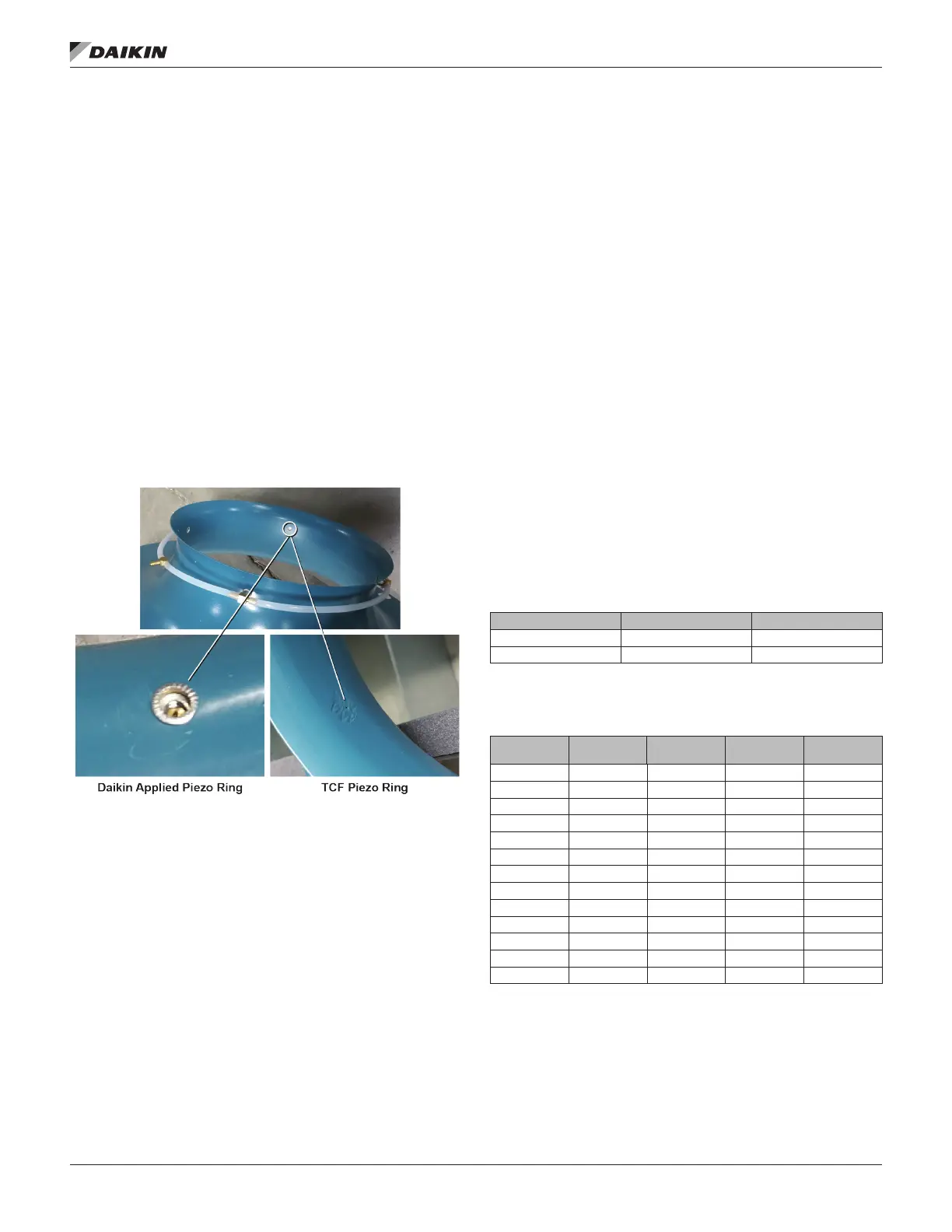
There are two manufacturer options for the piezometer
ring. Care should be taken to ensure that the
appropriate coecients are used, otherwise airow
measurement may be incorrect. Reference Figure 46
to determine which piezometer ring you have.
Figure 46: Determining the Manufacturer
Non-Standard Density Method
The following equation is used to measure the ow for non-
standard density:
ACFM = C1 × A × √(ΔP/ρ)
where: A = Inlet funnel throat area (square feet) - from Table 14
and Table 16
ΔP = The dierential in static pressure from the piezometer ring
and the inlet pressure tap (inches w.g.)
ρ = Air density (pounds mass/cubic foot)
C1 = Value from Table 13 and Table 15
Standard Density Method
The equation can be simplied by assuming standard
density and assuming funnel dimensions match the drawing
dimensions. Table 14 and Table 16 show the factor (F) for each
fan size and type. The equation then becomes the following:
For standard air (ρ = 0.075 lb/ft3):
ACFM = F × √ (ΔP)
where: F = factor from Table 14 and Table 16
ΔP = The dierential in static pressure from the piezometer ring
and the front pressure tap (inches w.g.)
Table 13: DDPL Factors For Free and Ducted Inlet —
Non Standard Density Method, TCF Piezo Ring
Product
DDPL Size 11-16 753.06 794.06
DDPL Size 18-44 692.03 740.14
Table 14: DDPL Factors For Free and Ducted Inlet —
Standard Density Method, TCF Piezo Ring
Free Inlet F
Ducted
Inlet F
Area A
Wheel
Diameter
11 and 12 944.92 996.36 0.344 12.40
15 1206.40 1272.08 0.439 14.00
16 1518.58 1601.26 0.552 15.75
18 1821.92 1948.58 0.721 18.25
20 2185.80 2337.76 0.865 20.00
22 2713.93 2902.60 1.074 22.25
24 3285.02 3513.39 1.300 24.50
27 3997.61 4275.53 1.582 27.00
30 4945.21 5289.01 1.957 30.00
33 5968.62 6383.56 2.362 33.00
36 7290.21 7797.03 2.885 36.50
40 8869.55 9486.16 3.510 40.25
44 10827.92 11580.68 4.285 44.50