24 | Technical data
Installer and user reference guide
132
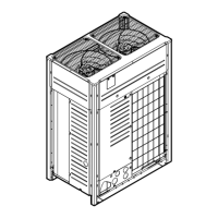
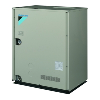
RKXYQ5T8+8T7Y1B + RDXYQ5T8+8T7V1B
VRV IV heat pump for indoor installation
4P499898-1B – 2021.12
24 Technical data
▪ A subset of the latest technical data is available on the regional Daikin website
(publicly accessible).
▪ The full set of latest technical data is available on the Daikin Business Portal
(authentication required).
In this chapter
24.1 Piping diagram: Compressor unit and heat exchanger unit .................................................................................................. 132
24.2 Wiring diagram: Compressor unit .......................................................................................................................................... 134
24.3 Wiring diagram: Heat exchanger unit .................................................................................................................................... 137
24.1 Piping diagram: Compressor unit and heat exchanger unit
5HP
R2T
R3T
R1T
M1FM2F
Y1E
Y3E
R2T
M1C
R3T
R7T
R4T
Y1S
S1NPL
S1PH
S1NPH
R5T
f
f
l
c
b
f
g
a
d
f
m
h
f i
j
k
e
B
A
3D110524-1
A Heat exchanger unit
B Compressor unit
a Stop valve (gas) (circuit 2: to indoor units)
b Stop valve (liquid) (circuit 2: to indoor units)
c Stop valve (liquid) (circuit 1: to heat exchanger unit)
d Stop valve (gas) (circuit 1: to heat exchanger unit)
e Service port (refrigerant charge)
f Filter
g Subcool heat exchanger
h Pressure regulating valve
i Capillary tube
j Accumulator
k Compressor accumulator
l Heat exchanger
m Check valve

 Loading...


