26 | Technical data
Installer and user reference guide
152
RXMLQ8 + RXYLQ10~14T7Y1B*
VRV IV system air conditioner
4P543427-1A – 2020.10
English Translation
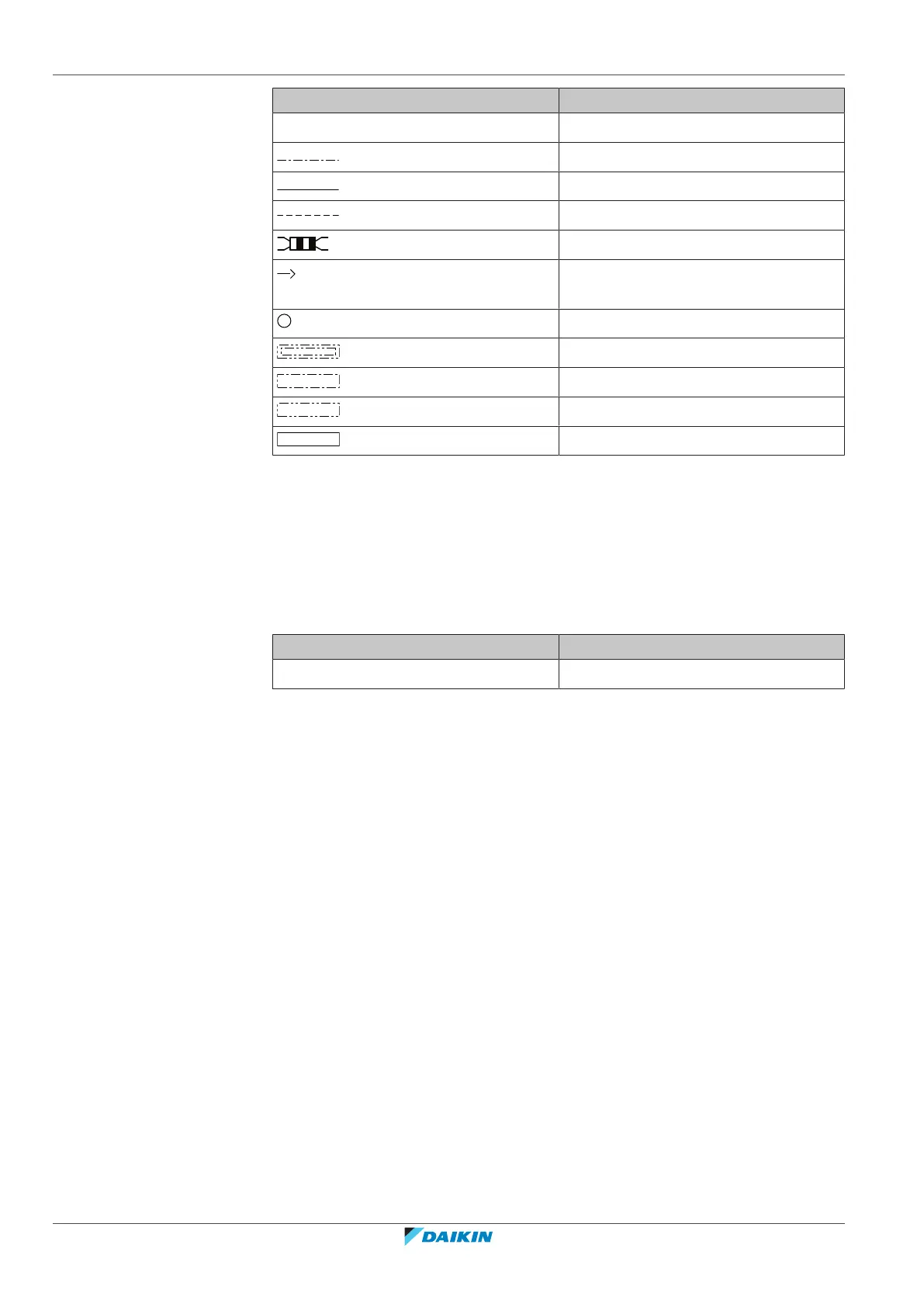
X1M Main terminal
Earth wiring
Wire number 15
Field wire
Field cable
Connection ** continues on page 12
column 2
Several wiring possibilities
Option
Not mounted in switch box
Wiring depending on model
PCB
1 Refer to the installation or service manual on how to use BS1~BS3 push
buttons, and DS1+DS2 DIP switches.
2 Do not operate the unit by short-circuiting protection device S1PH.
3 For connection of indoor-outdoor F1-F2 transmission wiring, and outdoor-
outdoor F1-F2 transmission wiring, refer to the service manual.
Position in switch box
English Translation
Position in switch box Position in switch box
Legend
A1P Main PCB
A2P Noise filter PCB
A3P Inverter PCB
A4P SUB PCB
A8P Adapter PCB
A9P * Cool/heat selector PCB
BS* (A1P) Push buttons (mode, set, return)
C* (A3P) Capacitor
DS* (A1P) DIP switch
E1HC Crankcase heater
F1S (A2P) Surge arrestor
F1U (A4P) Fuse (T, 3.15A, 250V)
F401U (A2P) Fuse (T, 6.3A, 250V)
F402U (A2P) Fuse (T, 6.3A, 250V)
F403U (A2P) Fuse (T, 6.3A, 250V)
F410U (A2P) Fuse (T, 63A, 600V)
 Loading...


