26 | Technical data
Installer and user reference guide
151
RXMLQ8 + RXYLQ10~14T7Y1B*
VRV IV system air conditioner
4P543427-1A – 2020.10
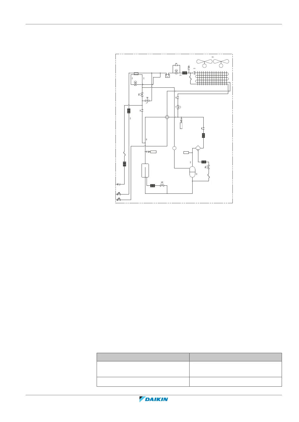
26.2 Piping diagram: Outdoor unit
Piping diagram: RXMLQ8 + RXYLQ10~14
R3T
R8T
R21T
R6T
R5T
R1T
R4T
d
c
b
c
d
h
j
i
f
p
q
o
g
l
e
k
a
r
M2F
M
M1F
M
R7T
R10T
M1C
m
n
S1NPL
S1NPH
S1PH
SV
SV
SV
SV
a Compressor (M1C)
b Heat exchanger
c Fan
d Fan motor (M1F, M2F)
e Accumulator
f Expansion valve, main (Y1E)
g Expansion valve, subcool heat exchanger (Y2E)
h Subcool heat exchanger
i Oil separator
j 4‑way valve, main (Y1S)
k Solenoid valve, oil accumulator (Y2S)
l Solenoid valve, oil1 (Y3S)
m Solenoid valve, injection (Y4S)
n Solenoid valve, hot gas (Y5S)
o Service port, refrigerant charge
p Stop valve (liquid)
q Stop valve (gas)
r Service port
26.3 Wiring diagram: Outdoor unit
The wiring diagram is delivered with the unit, located at the inside of the service
cover.
Notes to go through before starting the unit
English Translation
Notes to go through before starting the
unit
Notes to go through before starting the
unit
Symbols Symbols