18 | Piping installation
Installer and user reference guide
72
RXMLQ8 + RXYLQ10~14T7Y1B*
VRV IV system air conditioner
4P543427-1A – 2020.10
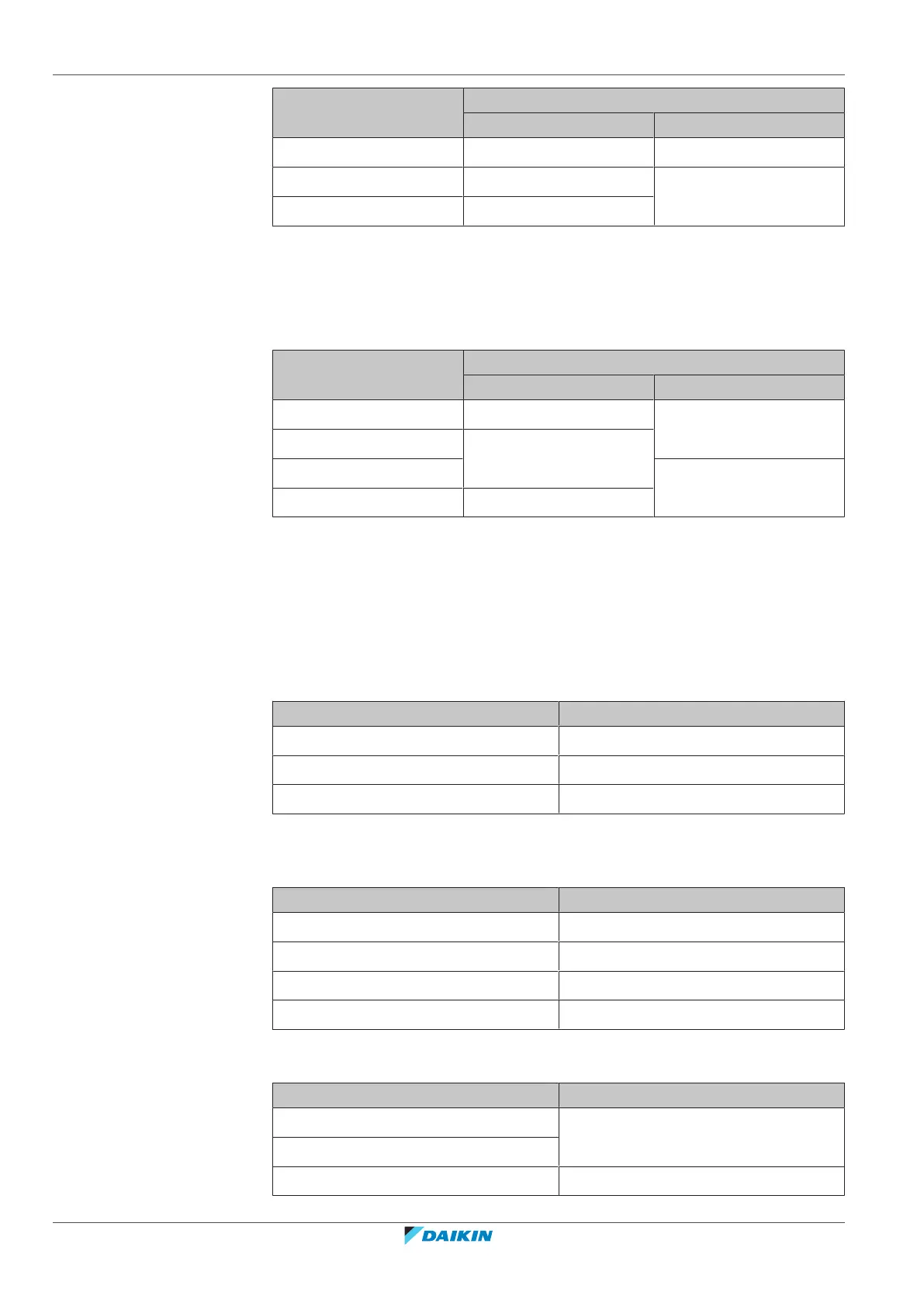
Total capacity index of
connected indoor units
Piping outer diameter size (mm)
Gas pipe Liquid pipe
20~62 12.7 6.4
63~149 15.9 9.5
150~208 19.1
Example:
Downstream capacity for F=[capacity index of unit 4]+[capacity index of unit 5]
G: Piping between branch selector box (BP box) and RA DX indoor unit
Only in case RADX indoor units are connected.
Indoor unit capacity index Piping outer diameter size (mm)
Gas pipe Liquid pipe
20, 25, 30 9.5 6.4
50 12.7
60 9.5
71 15.9
18.1.4 To select refrigerant branch kits
Refrigerant refnets
For piping example, refer to "To select the piping size"[469].
▪ When using refnet joints at the first branch counted from the outdoor unit side,
choose from the following table in accordance with the capacity of the outdoor
unit (example: refnet joint a).
Outdoor unit capacity type (HP) 2 pipes
8+10 KHRQ22M29T9
12~22 KHRQ22M64T
24~42 KHRQ22M75T
▪ For refnet joints other than the first branch (example refnet joint b), select the
proper branch kit model based on the total capacity index of all indoor units
connected after the refrigerant branch.
Indoor unit capacity index 2 pipes
<200 KHRQ22M20T
200≤x<290 KHRQ22M29T9
290≤x<640 KHRQ22M64T
≥640 KHRQ22M75T
▪ Concerning refnet headers, choose from the following table in accordance with
the total capacity of all the indoor units connected below the refnet header.
Indoor unit capacity index 2 pipes
<200 KHRQ22M29H
200≤x<290
290≤x<640 KHRQ22M64H
(a)