IOM 1281-2 • CENTRIFUGAL WATER CHILLERS 14 www.DaikinApplied.com
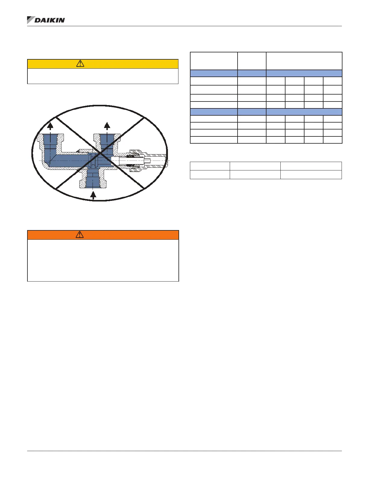
When the valve stem is not pushed forward or pulled back
Figure 8
CAUTION
Do not operate the system with the three-way valve stem in the Mid
Position.
Figure 8: Three-Way Valve, Mid Position
Oil Coolers
WARNING
This unit contains POE lubricants that must be handled carefully and the
proper protective equipment (gloves, eye protection, etc.) must be used
when handling POE lubricant. Failure to do so can result in personal injury.
POE must not come into contact with any surface or material that might
be harmed by POE, including certain polymers (e.g. PVC/CPVC and
polycarbonate piping).
Daikin Applied centrifugal chillers have a factory-mounted,
water-cooled oil cooler, temperature-controlled water regulating
valve and solenoid valve per compressor. All WDC units have
oil cooler connections located on the right hand tube sheet
under the evaporator Figure 9 or above the condenser Figure
10.
Field water piping to the inlet and outlet connections must be
installed according to good piping practices and include stop
installed. The water supply for the oil cooler should be from
the chilled water circuit or from a clean, independent source,
no warmer than 80°F (27°C), such as city water. When using
chilled water, it is important that the water pressure drop across
the evaporator is greater than the pressure drop across the oil
drop across the evaporator is less than the oil cooler, the oil
cooler must be piped across the chilled water pump, provided
oil cooler will be adjusted by the unit’s regulating valve so that
the temperature of oil supplied to the compressor bearings
(leaving the oil cooler) is between 95°F and 105°F (35°C and
40°C).
Table 4: Oil Cooler Data
Hot Side
POE
Lube
Cold Side Water Options to
079 - 087
Flow, gpm 9.9 11.9 2.9 2.0 1.54
Inlet Temp, °F 118.0 80.0 65.0 55.0 45.0
Outlet Temp, °F 100.0 87.3 94.5 98.3 101.4
Pressue Drop, psi - 4.3 0.3 0.14 0.09
100 - 126
Flow, gpm 15.8 21.9 5.1 3.5 2.7
Inlet Temp, °F 120.0 80.0 65.0 55.0 45.0
Outlet Temp, °F 100.0 87.0 95.0 99.0 102.3
Pressue Drop, psi - 3.78 0.23 0.11 0.07
Table 5: Cooling Water Connection Sizes
Model WDC 079-087 WDC/WCC 100-126
Conn Size 1 in. 1 1/2 in.
Compressors using chilled water for oil cooling will often start
loop temperature is pulled down. Data given above includes
that condition. As can be seen, with cooling water in the 45°F
to 65°F (7°C to 18°C) range, considerably less water will be
used, and the pressure drop will be greatly reduced.
When supplied with city water, the oil piping must discharge
through a trap into an open drain to prevent draining the cooler
by siphoning. The city water can also be used for cooling tower
makeup by discharging it into the tower sump from a point
above the highest possible water level.
NOTE: Particular attention must be paid to chillers with
In this case an auxiliary booster pump can be used or
city water employed.