www.DaikinApplied.com 7 IOM 1281-2 • CENTRIFUGAL WATER CHILLERS
Installation
Receiving and Handling
The unit should be inspected immediately after receipt for
possible damage.
All Daikin Applied centrifugal water chillers are shipped FOB
factory and all claims for handling and shipping damage are
the responsibility of the consignee. For knockdown options,
• The unit nameplate is located on the side of the Unit
Control Panel. It has a Style No. and Serial No.; both
are unique to the unit. These numbers should be used to
identify the unit for service, parts, or warranty questions.
This plate also lists the unit refrigerant charge.
• Vessel nameplates are located on the evaporator and
condenser, listing National Board Number (NB) and serial
number. Either number can identify the vessel (but not
the entire unit).
• A compressor nameplate is located on each compressor.
Insulation corners from the evaporator’s rigging hole locations
are shipped loose and should be glued in place after the unit is
Check that these items have been delivered with the unit.
If so equipped, leave the shipping skid in place until the unit is
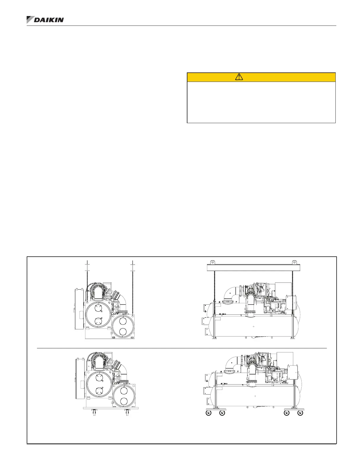
Lifting and Rigging
CAUTION
Extreme care must be used when rigging the unit to prevent
damage to the control panels and refrigerant piping. See the
the weights and center of gravity of the unit. If the drawings
for assistance.
Spreader bars must be used between the rigging lines to keep
lifting straps vertical and prevent damage to the control panels,
electrical panels, unit piping,and motor terminal boxes. The unit
can be lifted by fastening rigging hooks to the outermost four
rigging holes (see Figure 1). The spreader-bar length should
be equal to, or no more than 1-foot shorter than, the distance
between the lifting holes located at opposite ends of the chiller.
The unit will require a double spreader-bar of this length
capable of supporting 1.5 times the shipping weight of the unit.
Separately, all cables and hooks by themselves must also be
capable of supporting 1.5 times the shipping weight of the unit.
NOTE: The spreader bars in Figure 2 are a representation
spreader bars needed.
If a knockdown option was ordered on the unit, reference the
section starting on page 25 for more
information.
Figure 2: Representative Unit Lifting and Rigging
BACK VIEW
END VIEW
BACK VIEW
END VIEW
NOTES:
DAIKIN APPLIED IS NOT A LICENSED NOR CERTIFIED RIGGING SPECIALIST. IT IS THE CUSTOMER'S
1.
RESPONSIBILITY TO CONSULT A CERTIFIED RIGGING CONTRACTOR TO RIG, LIFT, AND MOVE COMPONENTS &
SUBCOMPONENTS PROPERLY AND SAFELY.
LIFT THE UNIT BY ATTACHING CHAIN HOISTS TO THE ROUND LIFTING HOLES LOCATED ON THE TUBESHEETS.
2.
FULL UNIT - LIFTING
FULL UNIT - RIGGING