IOM 1281-2 • CENTRIFUGAL WATER CHILLERS 28 www.DaikinApplied.com
NOTE: Drawings, dimensional values, and other information
selected. Refer to the as-built submittal drawings
provided by a Daikin Applied sales representative for
The compressor dimensions vary by model. All dimensions and
weights per compressor are listed in Table 8.
Figure 24: Representation - Compressor Dimensions
Table 8: Dimensions for Compressors
Follow the steps listed to remove and re-attach each
compressor.
1. Prior to detaching or unsweating any connections, verify
there is no pressure or charge in the lines.
2.
3.
4.
compressor and evaporator connection points.
5.
cap at the compressor gear housing and condenser
connection points; see Figure 25.
6.
caps at the compressor motor housing and evaporator
a minimum of 2 places to prevent damage.
7.
the compressor gear housing connections; see Figure
25
condenser connections.
8.
the discharge nozzle and evaporator connection points.
Care must be taken when brazing or removing lines to
not apply excessive heat to valve seats; use cooling
wraps at all times on valve components.
9. Disconnect power leads from starter.
10. Loosen and remove bolts on the top side of the
compressor discharge nozzle (see Figure 26
11.
remove discharge piping.
12.
entering.
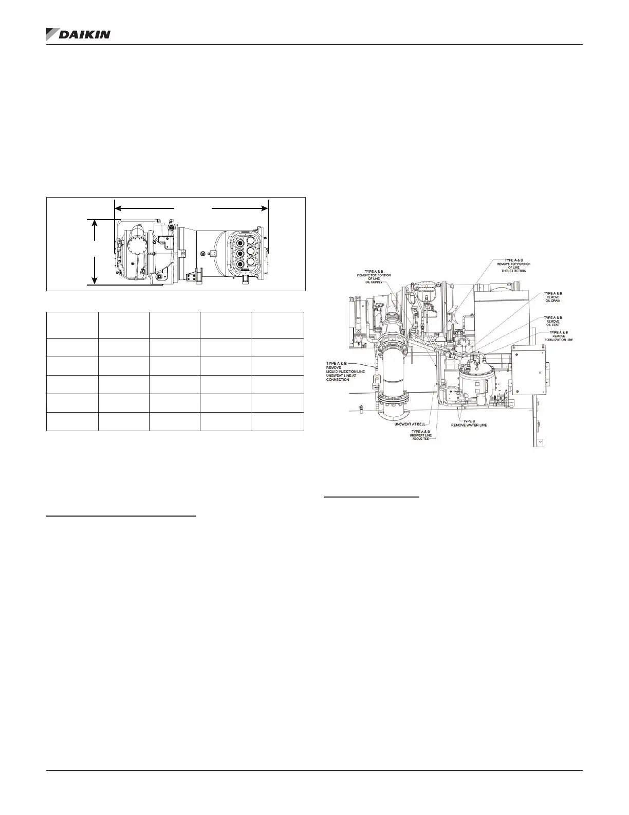
Figure 25: Oil Cooler Line Identications
NOTE: Graphic is representative. Line locations may vary by
1. Loosen and remove bolts/screws on either side of the
suction elbow (see Figure 26).
2. Loosen the (8) bolts from the compressor’s bottom
mounting feet (see Figure 26).
3. Use lifting straps on the compressor assembly Figure 23
to rig compressor for removal. Compressor dimensions
and weights are given in Table 8.
LENGTH
HEIGHT
Comp Size
Length
in (mm)
Width
in (mm)
Height
in (mm)
Weight
lb (kg)
079 64.9 (1648) 32.3 (821) 25.1 (638) 3200 (1451)
087 64.9 (1648) 32.3 (821) 25.1 (638) 3200 (1451)
100 87.5 (2224) 43.2 (1097) 31.0 (788) 6000 (2721)
113 87.5 (2224) 43.2 (1097) 31.0 (788) 6000 (2721)
126 87.5 (2224) 43.2 (1097) 31.0 (788) 6000 (2721)