www.DaikinApplied.com 47 IOM 1281-2 • CENTRIFUGAL WATER CHILLERS
The Active Leaving Water variable is set equal to the Cool LWT
setpoint if the reset signal is less than or equal to 4 mA. It is set
equal to (Cool LWT setpoint + Max Reset Delta T setpoint) if
the reset signal equals or exceeds 20 mA. The Active Leaving
Water variable will vary linearly between these extremes if the
reset signal is between 4 mA and 20 mA. An example of this
action is shown in Figure 49; temperatures are examples only.
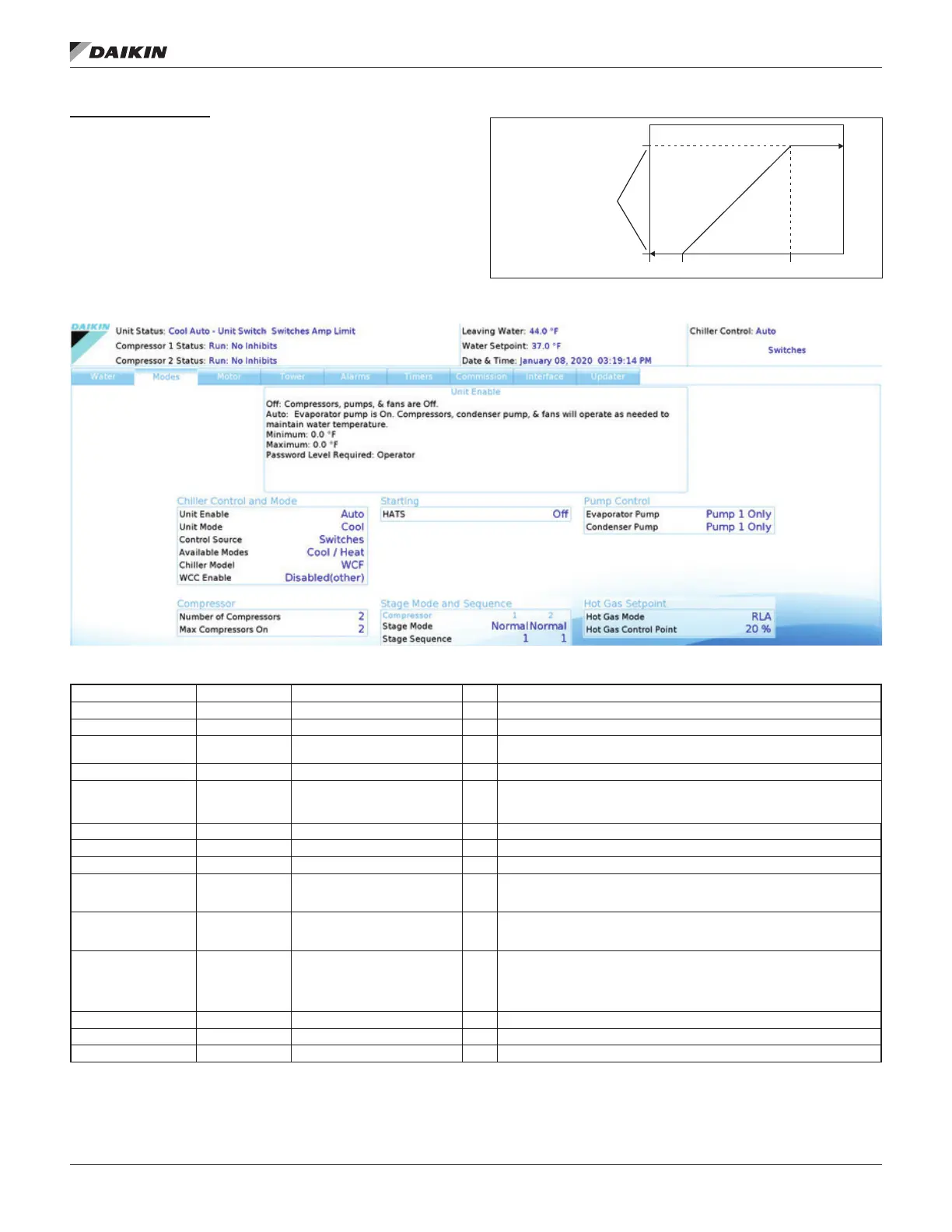
Figure 49: LWT Reset (Cool Mode)
Figure 50: Settings View - Modes
Table 13: Modes Setpoints
Description Default Range PW
Chiller Model WCF WCF, WMC T WCF is the general software model for WDC, WCC and TDC
WCC Enable Disabled (other) Enabled (WCC), Disabled (other) T Will always be Disabled for WDC chillers
Unit Enable OFF OFF, AUTO O
as required to meet LWT
Control Source Switches Switches, Local, Network BAS O Sets control source. See Figure 35 on page 37
Available Modes Cool with Glycol
Cool Only, Cool w/ Glycol, Cool/
Ice w/ Glycol, Ice Only w/ Glycol,
Cool/Heat, Heat Only
M See Water Setpoints,Table 12, for control temperature targets for each mode
No. of Compressors 2 1 to 2 T Models will be set to 2 as a default.
Max Compressors On 2 0 to 8 M Max number of compressors that can be on local pLan chiller network
HATS - Starting M High Ambient Tandem Start
Condenser Pump
Primary
M
Evaporator Pump
Primary
M
Stage Mode Normal M
fails.
Stage Sequence 1 0-99 M
Hot Gas Mode RLA T
Hot Gas Control Point 20% 20 to 70% T Sets hot gas control point %
4 ma
20 ma
Cool LWT Setpoint
(44.0°F)
Max Reset Delta T
(10.0°F)
(54.0°F)
0 ma