IOM 1281-2 • CENTRIFUGAL WATER CHILLERS 52 www.DaikinApplied.com
To set up in HMI,
A. The TOWER Setpoint setting for Cooling Tower Control
strategy should be NONE. Tower Valve/VFD should be
changed to VALVE STAGE.
Tower Valve Type. Select NC or NO depending if valve
is normally closed to the tower with no control power or
normally open to the tower with no control power.
B. Use all of the same setpoint settings as outlined in
Strategy (II) - section B for Temp or section C for Lift. In
addition, set the following:
a. Set VFD Stage Up (valve position % open) above
b. Set Stage Down (valve position % closed) below
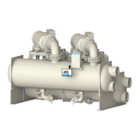
Figure 57: Strategy (III) - VALVE STAGE
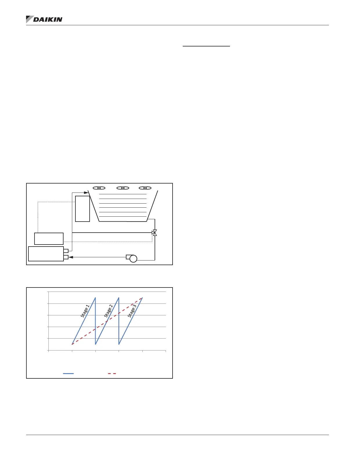
Figure 58: Strategy (III) VALVE STAGE - Valve Opening vs.
Temperature
As shown in Figure 58, the default minimum and maximum
valve opening positions are 10% and 90%, respectively. These
minimum and maximum positions are adjustable anywhere
between 0% and 100%. Additional fans stage on when the
valve opening position reaches the maximum value that was
set.
Strategy (IV) NONE:
This control strategy is tower fan staging only. This is not a
recommended strategy. In this mode the tower fan staging
(up to three stages) is controlled by either the condenser
Entering Water Temperature (EWT) or LIFT pressure
Tower bypass or fan speed are not controlled. See Figure 59
and Figure 60.
To set up in HMI,
The following settings are used for the Tower Fan Staging Only
mode:
1. Select TEMP if Cooling Tower Control is based on
condenser EWT or LIFT if based on compressor lift
expressed in pressure.
2. Set Tower Valve/VFD as NONE for no bypass valve or
fan VFD control.
3. Set Cooling Tower Stages as one to three fan outputs
depending on the number of fan stages to be used.
More than one fan can be used per stage through the
use of relays.
4. Select Fan Stage Up Time from 1 to 60 minutes. The
default value of 2 minutes is a good starting point. The
value may need to be adjusted later depending on
actual system operation.
5. Select Fan Stage Down Time from 1 to 60 minutes.
The default value of 5 minutes is a good starting point.
The value may need to be adjusted later depending
on actual system operation.
If TEMP is selected for Cooling Tower Control, use:
a.
b. Set the Stage Fan On temperatures consistent with
the temperature range over which the condenser
EWT is desired to operate. The default values of
70°F, 75°F, and 80°F are a good place to start in
climates with moderate wet bulb temperatures. The
number of Stage Fan On setpoints used must be
the same as the number of Cooling Tower Stages.
If LIFT is selected for Cooling Tower Control, use
a.
b. Set the Stage Fan On pressures starting with
default setpoints. The number of Stage Fan On
setpoints used must be the same as the number of
Cooling Tower Stages.
Condenser
Bypass Line
0-10 VDC Signal
Bypass
Valve
Cooling Tower
Fan Staging
(Up to 3 fans)
MicroTech
®
Controller
Tower
Control
Panel
0
20
40
60
80
100
65 70 75 80 85 90
Valve Opening (%)
Temperature (°F)
3 Fan Stages 1 Fan Stage