IOM 1281-2 • CENTRIFUGAL WATER CHILLERS 68 www.DaikinApplied.com
1. Re-sample after 500 hours of unit operation. If content
sample at normal interval. If content increases between
after an additional 500 hours of operation. If content
increases 25% or more, inspect compressor.
2. Re-sample after 500 hours of unit operation. If content
sample at normal interval. If content increases between
additional 500 hours of operation. If content increases
25% or more, monitor for water leak. Since POE
lubricants are hygroscopic, many times the high moisture
level is due to inadequate handling and packaging.
The TAN reading MUST BE USED in conjunction with
moisture readings.
3. For TAN between .10 and .19, re-sample after 1000
hours of unit operation. If TAN increases above 19,
normal interval.
Flow Switch Installation and Calibration
pressure switches but care must be taken regarding wiring.
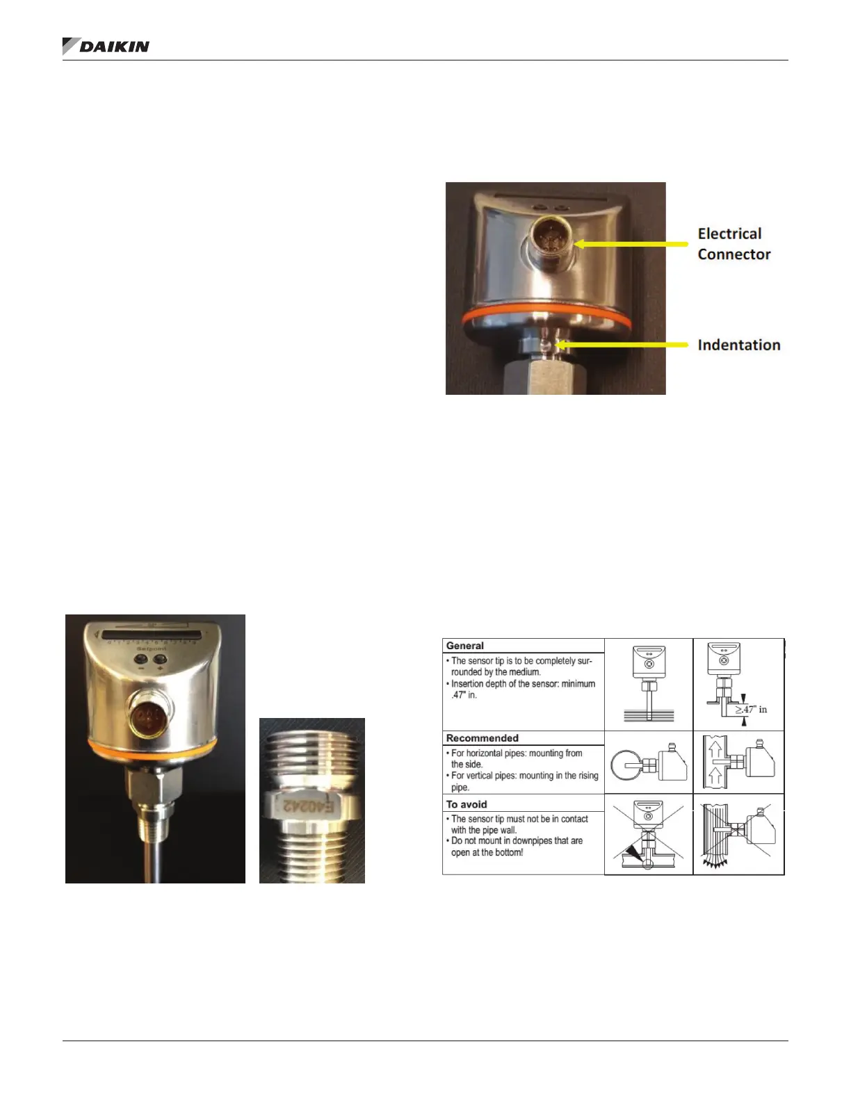
switch and an adapter labeled E40242 by the supplier.
Figure 70: Thermal Dispersion Flow Switch and Adapter
Mounting
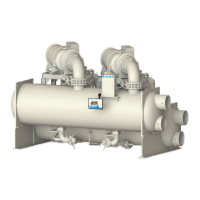
Figure 71 highlights the position of the electrical connector and
electrical connection and indentation ‘mark’ are oriented as
recommended in Figure 72
on the bottom of a horizontal pipe.
Figure 71: Flow Switch Details
sensor should be mounted on the wall of the inlet pipe of
evaporator and condenser, or in a run of straight pipe that
allows 5 to 10 pipe diameters prior to the sensor and 3 to 5
pipe diameters of straight pipe after the sensor. Flow switch
installation on the outlet pipe is necessary, contact Chiller
Technical Response at TechResponse@DaikinApplied.com to
review the jobsite details.
NOTE:
If issues exist, contact Chiller Technical Response at
TechResponse@DaikinApplied.com.
Figure 72: Remote Mounting Guidelines for Flow Switch
If needed, the adapter is threaded into the pipe using pipe
mounted onto the adapter using silicone grease. Carefully
apply lubricant to the inside threads and o-ring so temperature
probe does not become coated with lubricant. Torque the
adapter/sensor connection to 18.5 ft/lbs.
IMPORTANT: Flow switch
MUST be calibrated before
chiller operation. Failure to
properly calibrate the switch
may result in severe chiller
damage and/or void warranty.