5
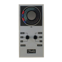
HEATING SWITCH
(d) With selector switch in ON position, terminal 2
should be LIVE.
(e) With selector switch in OFF position, terminal 3
should be LIVE.
(f) With selector switch in TIMED position, terminal
2 should be LIVE between tappets A-B and C-D
and terminal 3 should be LIVE between tappets
B-C and D-A.
9. Remove cut-out from bottom of outer case as
required. Refi t outer case and selector switch fi xing
rings. Check that outer case sits squarely on body and
is not distorted by an uneven wall surface.
10. Rotate dial clockwise through at least one complete
revolution and check that all four tappets are clear of
outer case aperture.
11. Ease of installation can be achieved by the use of the
Danfoss Randall Wiring Centre which is obtainable
from most Builders Merchants and Distributors.
NOTE: If a Wiring Centre is used follow the
installation instructions included with that
unit and not the wiring diagrams overleaf.
!
Installation