AK-CT 450A User Guide RS8GR602 © Danfoss 2016-10 37
Input signal on DI5. Contact switch. See DI3 above P56
1 1 1 1 1 1 1 1
0 19 0
Input signal on DI6. Contact switch. See DI3 above P57
1 1 1 1 1 1 1 1
0 19 0
Input signal on DI7. High voltage signal. See DI3 above P58
1 1 1 1 1 1 1 1
0 19 0
Input signal on DI8. High voltage signal. See DI3 above P59
1 1 1 1 1 1 1 1
0 19 0
Max. opening time of night blind following manual override
with DI activation.
P60
1 1 1 1 1
0 min. 60 min. 5
Erase all current controller settings on ID module. P61
1 1 1 1 1 1 1 1
0 / o 1 / on 0 / o
Conguration of night blind relay. On= night blind used P64
1 1 1 1 1
0 / o 1 / on 1 / on
Stop time for fan while night blind rolls down P65
1 1 1 1 1
0 sec 300 sec 60
Max. on time for light and night blind following manual
DI activation
P66
1 1 1 1 1 1 1 1
0 min. 60 min. 30
Real time clock t-
Six start times for defrost.
Setting of hours.
0=OFF
t01 -
t06
1 1 1 1 1 1 1 1 0 hrs 23 hrs 0
Six start times for defrost.
Setting of minutes.
0=OFF
t11 -
t16
1 1 1 1 1 1 1 1 0 min. 59 min. 0
Clock - Setting of hours t07 1 1 1 1 1 1 1 1 0 hrs 23 hrs 0
Clock - Setting of minute t08 1 1 1 1 1 1 1 1 0 min. 59 min. 0
Clock - Setting of date t45 1 1 1 1 1 1 1 1 1 day 31 day 1
Clock - Setting of month t46 1 1 1 1 1 1 1 1 1 mon. 12 mon. 1
Clock - Setting of year t47 1 1 1 1 1 1 1 1 0 year 99 year 0
Service u-
Temperature measured with S5 sensor
u09 1 1 1 1 1 1 1 1
Status on DI1 input. on/1=closed
u10 1 1 1 1 1 1 1 1
Actual defrost time (minutes)
u11 1 1 1 1 1 1 1 1
Temperature measured with S3 sensor
u12 1 1 1 1 1 1 1 1
Status on night operation (on or o) 1=on
u13 1 1 1 1 1 1 1 1
Temperature measured with S4 sensor
u16 1 1 1 1 1 1 1 1
Thermostat temperature
u17 1 1 1 1 1 1 1 1
Run time of thermostat (cooling time) in minutes
u18 1 1 1 1 1 1 1 1
Opening degree of EVR valve ** u23 1 1 1 1 1 1 1 1
Temperature measured with S6 sensor
(product temperature)
u36 1 1 1 1 1 1 1 1
Status on DI2 input. on/1=closed
u37 1 1 1 1 1 1 1 1
Air temperature . Weighted S3 and S4
u56 1 1 1 1 1 1 1 1
Measured temperature for alarm thermostat
u57 1 1 1 1 1 1 1 1
Status on relay for cooling
** u58 1 1 1 1 1 1 1
Status on relay for fan
** u59 1 1 1 1 1 1 1 1
Status on relay for defrost
** u60 1 1 1 1 1 1 1
Status on relay for rail heat
** u61 1 1 1 1 1 1 1 1
Status on relay for alarm
** u62 1 1 1 1 1 1 1 1
Status on relay for light
** u63 1 1 1 1 1 1 1 1
Status on relay for hot gas valve
** u64 1
Status on relay for compressor 2
** u67 1
Temperature measured with S5B sensor u75 1 1 1 1 1 1 1 1
Temperature measured with S3B sensor u76 1 1 1 1
Temperature measured with S6B sensor u79 1 1 1 1
Status on relay for hot gas valve / drain valve ** u80 1
Status on relay for heating element in drip tray ** u81 1
Status on relay for night blinds ** u82 1 1 1 1 1
Status on relay for defrost 2 ** u83 1 1 1
Readout of the actual rail heat eect
u85 1 1 1 1 1 1 1 1
1: Thermostat 1 operating, 2: Thermostat 2 operating
u86 1 1 1 1 1 1 1 1
Status on DI3 input. on/1=closed u87 1 1 1 1 1 1 1 1
Readout of thermostats actual cut in value
u90 1 1 1 1 1 1 1 1
Readout of thermostats actual cut out value
u91 1 1 1 1 1 1 1 1
Measured temperature for alarm thermostat in section B U34 1 1 1 1
Air temperature in section B U35 1 1 1 1
Status of relay for light 2 ** U36 1 1 1 1 1 1
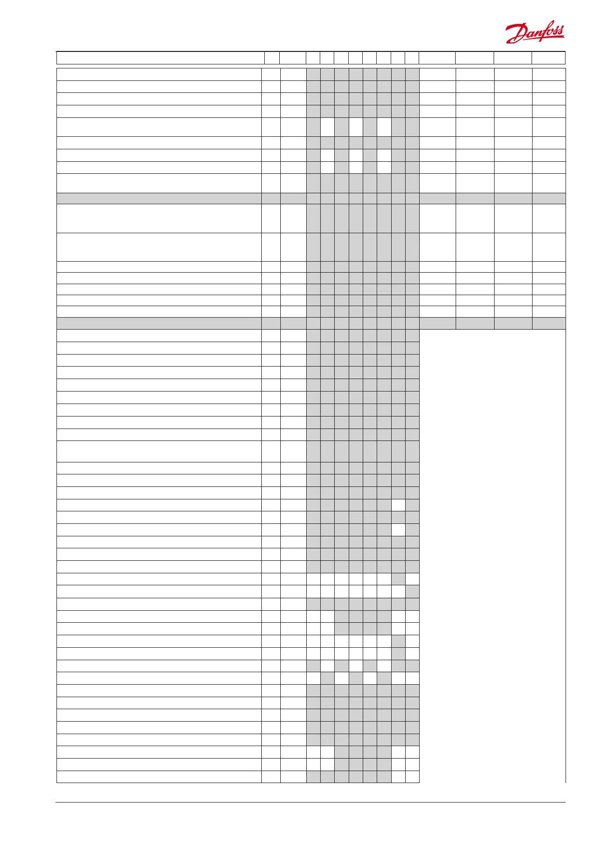
Continued Code 1 2 3 4 5 6 7 8 Min. Max. Fac. Actual
 Loading...